53
CHAPTER 6: The Menu System
•
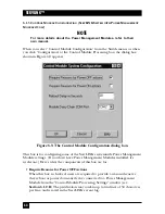
Control Module Configuration
Select this option to configure any Power Management Modules attached to
the ServLINK. You can force the Modules to require justification for power-
related actions; specify the number of seconds that a computer will be off
when the power is cycled; or specify the COM port where the first
Management Module is attached to the ServLINK. See
Section 6.1.3
.
6.1.1 S
WITCH
PC
S
6.1.1.A The Main Dialog Box
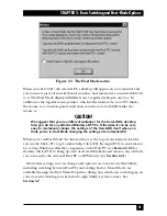
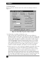
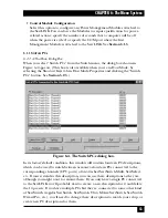
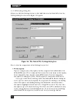
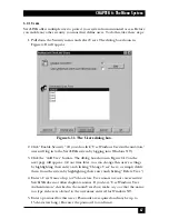
When you select “Switch PCs” from the Switch menu, the dialog box shown in
Figure 6-4 appears. (This box is also available when you’re in Host Mode, by
selecting the Shortcut Keys tab in Host Mode Properties and clicking the “Switch
PCs” button. See
Section 5.2.3
.)
Figure 6-4. The Switch PCs dialog box.
In its factory-default condition, this window will contain fourteen PC descriptions,
which can be used to switch between as many as fourteen PCs connected to the
corresponding channels (CPU ports) of an attached ServSwitch Multi, ServSelect,
etc. If your system fits this description, you can use these descriptions as they are,
although you might want to rename them. If you only have a single PC connected
to the ServLINK, you’ll probably want to create a new description for it and delete
the 14 presets. If you have multiple PCs but they’re connected to some other kind
of ServSwitch (regular ServSwitch, ServSwitch Ultra, Matrix ServSwitch, ServSwitch
Wizard Pro, etc.), you’ll need to change these descriptions to match your setup, or
create new PC descriptions for them.
Summary of Contents for ServLink ACR3500A
Page 111: ...NOTES ...
Page 112: ...NOTES ...
Page 113: ...NOTES ...
Page 114: ...NOTES ...
Page 115: ...NOTES ...


