


27
CHAPTER 3: Installation
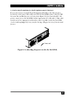
3.1.7.C After Installing the Modules
Once you’ve installed all your Modules, cables, power cords, etc., your power-
managed ServLINK system should be ready to be powered up. When you do so
(see the next section), the ServLINK’s control software will automatically sense that
you’ve added the Power Management Modules. Refer to
Section 5.1.3
for
instructions on configuring the Modules.
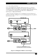
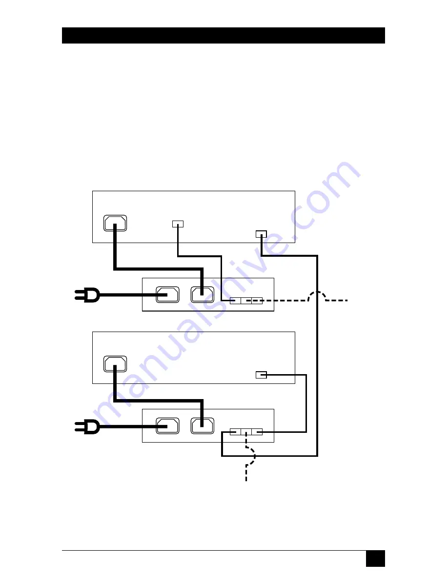
Figure 3-12 shows the logical layout of a ServLINK system that includes Power
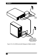
Management Modules, and Figure 3-13 (on the following page) shows the physical
layout of such a system.
Figure 3-12. Management-Module connection logic.
IN
OUT
IN OUT
SERIAL
DATA
ACCESS CONTROL CARD
DATA
RS232 COMM
IN
OUT
IN OUT
SERIAL
DATA
RS232 COMM
OTHER SYSTEMS
MODEM
POWER MANAGEMENT MODULE
SERVLINK UNIT
SERVER PC
POWER MANAGEMENT MODULE
SERVLINK’S DEDICATED
FIRST DEVICE’S
OPTIONAL
OTHER DEVICES’ POWER MANAGEMENT MODULES,
PASS-THROUGH DEVICE AT END OF CHAIN IF DESIRED
Summary of Contents for ServLink ACR3500A
Page 111: ...NOTES ...
Page 112: ...NOTES ...
Page 113: ...NOTES ...
Page 114: ...NOTES ...
Page 115: ...NOTES ...