35
CHAPTER 4: Configuration
8. Click the “OK” button to save the address macro to the ServLINK’s memory.
Repeat steps 3 through 8 for each PC whose address you want to add to the
ServLINK’s memory. Click the “Exit” button in the “Create Keyboard Macro” box
to go back to the Main Menu when you’re done. Now take one last set of steps:
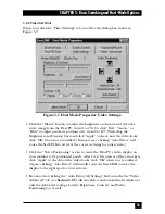
9. Pull down the Switch menu and choose the “Switch PCs” option. This will
bring up the “Switch PCs” dialog box ( a list of PCs connected to the
ServLINK).
10. To add a new computer, click the “Add” button.
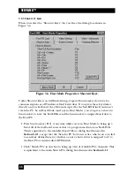
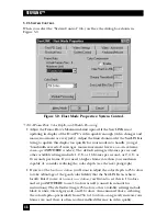
11. The “PC Settings” dialog box will appear. In the “PC Description” field, enter
a description for this computer. In KVM-switched systems, it’s generally best
to use the same description for each PC as the one (if any) assigned to that
PC in the menu system of the KVM switch.
12. In the “Switch Box Command” field, make sure that you have selected the
hotkey combination that initiates command mode for your switch. The
default is set for [Num Lock] and keypad minus [–].
If you have a single PC attached to the ServLINK,
select “Switch Box Not
Applicable.”
13. In the “Switch Box Select PC” field, select your channel address out of the
drop-down menu. Channels that you configured in the previous section
should appear in this menu.
If you have a single PC attached to the ServLINK,
select “Switch Box Not
Applicable.”
14. The remaining settings in this menu are automatically generated and should
not under normal circumstances be changed. Select “OK” to take you back to
the main Switch PCs box (“List of PCs”).
15.
If you have multiple KVM-switched computers attached to the ServLINK,
repeat
steps 10 through 14 for every computer you want to add to the list.
16. When you’re finished, click “Exit” to return to the Main Menu.
Summary of Contents for ServLink ACR3500A
Page 111: ...NOTES ...
Page 112: ...NOTES ...
Page 113: ...NOTES ...
Page 114: ...NOTES ...
Page 115: ...NOTES ...


