


26
SERVLINK™
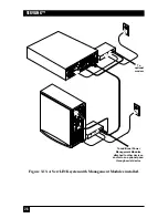
4. (Optional) Plug one end of the other RJ-45 cable included with the Module
into the port marked “SERIAL” on the Module you’re installing. Take the
other end of this cable and attach one or more of the Module’s included
adapters (or identical ones if you’ve already used any of them—call Black Box
Tech Support for extras) to connect to a serial device or a device’s serial port
in any of these ways:
•
To connect to the serial port of the Module’s attached PC, router, network switch, etc.
(the standard application) or to the serial port of another such device:
Attach the
included RJ-45F-to-DB9F adapter to the cable and plug the adapter into the
device’s DB9M serial port. (If the device has a DB25M serial port instead,
you’ll also need a non-included DB9M-to-DB25F adapter.)
•
To connect to a modem, multiplexor, or other RS-232 DCE with a DB25F connector:
Attach the included RJ-45F-to-DB9M adapter to the cable, then add the
included DB9F-to-DB25M adapter. Plug the DB25M end of the adapter
assembly into the device.
•
To connect to any other RS-232 device that can be connected to a PC’s serial port:
Attach the included RJ-45F-to-DB9M adapter to the cable, then (if
necessary) add the included DB9F-to-DB25M adapter. Get any cable,
adapters, etc., that you’d run from a PC’s DB9M or DB25M serial port to
the device. Plug these into the DB9M or DB25M end of the Module’s
adapter assembly and run them to the device. (Keep in mind that the
normal distance limit for RS-232 communication is 50 ft. [15.2 m].)
5. (Optional)
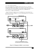
If this is the last Management Module in the daisychain:
Plug one end
of an RJ-45 cable (the other included one if you didn’t already use it in step 4,
one just like it otherwise) into the “DATA OUT” port of this Module. Take
the other end of this cable and attach one or more of the Module’s included
adapters (or identical ones if you’ve already used any of them—call Black Box
Tech Support for extras) to connect to a “pass-through” serial device that you
can communicate with when none of the Power Management Modules are
active. Refer to the “bullet points” in step 4 above for how to do this.
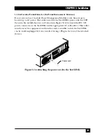
6. Connect the male (inlet) end of the Module’s included power patch cord to
the port marked “POWER OUT” on the back of the Management Module.
7. Connect the female (outlet) end of this cord to the power inlet on the device
that the Module will be controlling.
8. Finally, run the device’s power cord from its own inlet to a properly rated wall
outlet.
Summary of Contents for ServLink ACR3500A
Page 111: ...NOTES ...
Page 112: ...NOTES ...
Page 113: ...NOTES ...
Page 114: ...NOTES ...
Page 115: ...NOTES ...