background image

BAFWORKS

®

 INSTALLATION GUIDE

WWW.BIGASSSOLUTIONS.COM     ©2013 DELTA T CORP.     ALL RIGHTS RESERVED

52

Adding and deleting light groups

To add a light group:

1. 

On the BAFWorks

®

 home screen, touch 

Lights

.

2.  In the top left corner of the screen, touch 

Edit

.

3. 

Enter the admin lock password, and then touch 

OK

Note: The default admin lock password is 1271. See page 55 for instructions on 

changing the password.

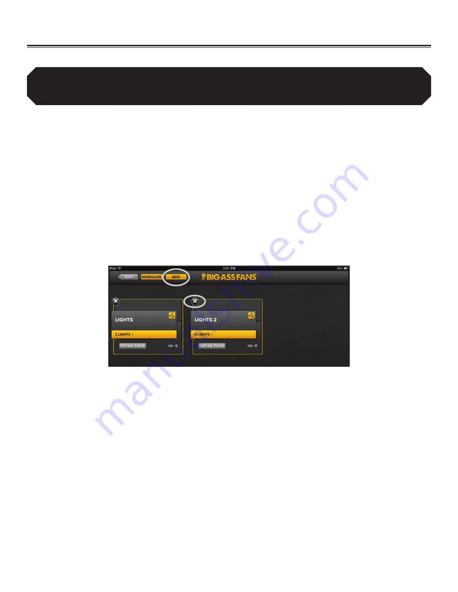
4.  At the top of the screen, touch 

Add 

(Figure 13).

5. 

In the Create New Group dialog box, enter a name for the new group, and then select 

Lights

 for the group type.

6.  Touch 

Save

. The new group appears on the light groups screen.

7.  In the top left corner of the screen, touch 

Exit

.

To delete a light group:

1. 

On the BAFWorks home screen, touch 

Lights

.

2.  In the top left corner of the screen, touch 

Edit

.

3. 

Enter the admin lock password, and then touch 

OK

Note: The default admin lock password is 1271. See page 55 for instructions on 

changing the password.

4.  Touch the 

X

 icon(s) next to the light group(s) you want to delete (Figure 13).

5.  In the top left corner of the screen, touch 

Exit

.

Setting Up the BAFWorks

®

 Application (cont.)

Figure 13–Adding and deleting light groups

You can only delete empty light groups. You must delete all lights from a group or move the lights to a different group 

before you can delete the group. To move a light to a different group, select the light, and then choose a group from 

the drop-down header at the top of the light settings page (see page 65). For instructions on deleting lights, see the 

previous page.

Summary of Contents for BAFWorks 3.0

Page 1: ...INSTALLATION GUIDE For help call 1 877 BIG FANS or visit www bigassfans com BAFWORKS INSTALLATION GUIDE BAFWorks 3 0 For help call 1 877 BIG FANS or visit www bigassfans com...

Page 2: ...Customer Service 1 877 BIG FANS International 1 859 233 1271...

Page 3: ...ange without notice 2011 NETGEAR Inc All rights reserved All other trademarks used herein are the properties of their respective owners No part of this document may be reproduced or translated into a...

Page 4: ...removal or disconnection of a safety device the safety device is to be reinstalled or remounted as previously installed WARNING Power must be disconnected before installation and servicing cleaning an...

Page 5: ...24 Terminations at the Modbus Gateway 25 Setup and Wiring Delta E Series VFDs 26 Setup and Wiring Delta M Series VFDs 28 Setup and Wiring Lenze SMVector VFDs 30 RS 485 Network Biasing Lenze SMVector...

Page 6: ...Alarm System Trip Behavior 64 Configuring Individual Light Settings 65 Turning Light Groups On and Off 66 Configuring Light Group Settings 66 Scheduling Light Group Events 67 Configuring Individual L...

Page 7: ...quality form and function to solve problems in the built environment It means having a herd of engineers on staff and the world s only R D facility dedicated to testing air movement on a grand scale I...

Page 8: ...3 AI3 AGND AI4 AI4 AI5 AI5 AI6 AI6 AI7 AI7 V S GND RL2 NO RL2 COM RL2 NC RL3 NO RL3 COM RL3 NC RL4 NO RL4 COM RL4 NC RL5 NO RL5 COM RL5 NC N C V S GND RL1 NC RL1 COM RL1 NO RL0 COM RL0 NO NC Ethernet...

Page 9: ...Charger BAF Gateway 4 Resistor3 Wi Fi Router AC Power Adapter4 USB Splitter5 12 305 mm USB Cord6 12 305 mm CAT5 Ethernet Patch Cable 9 ft 2 7 m Power Cord Bushing Plug Foam Bumper 1 The iPad enclosure...

Page 10: ...PowerFlex 4 4M or 40 VFD 3 Included only if the remote operator station option is ordered One remote operator station is required for each fan you plan to control locally Four 4 cover screws and two...

Page 11: ...w the standard of Ethernet IP TCP port number 44818 is used for explicit messaging and UDP port number 2222 is used for implicit messaging 2 Identify hardware requirements Identify the hardware requir...

Page 12: ...on the same network Big Ass Solutions recommends obtaining and recording each module s MAC ID number The MAC ID numbers will be helpful during ADAM module configuration To obtain an ADAM module s MAC...

Page 13: ...stallation Fans on pages 23 36 If you are installing the remote operator station option complete all installation and wiring steps in Fan Remote Operator Station Optional on pages 37 41 4 Configure AD...

Page 14: ...duct warranty will not cover equipment damage or failure that is caused by improper installation CAUTION The following information is merely a guide for proper installation Big Ass Solutions cannot as...

Page 15: ...tactors or motor starters For loads that exceed the 5 A rating the relay outputs can be used to drive pilot or isolation relays to achieve higher current capacity Some typical wiring examples are show...

Page 16: ...buttons However relay contact flight time is critical If the pilot relay s N C contact re closes too quickly upon an iPad stop command relative to the motor starter s auxiliary contact opening the mot...

Page 17: ...ric representation of the contactor s coil lead functions The pilot relay s N O and N C contact are used to alternate the contactor s on and off coil leads This diagram can also be used as a basic gui...

Page 18: ...ght switch and low voltage SPDT pilot relay ADAM 6160 Relay Output Module Note ADAM 6160 relay module contacts are rated for 5 A max 250 VAC The relay module contacts can be used to pilot smaller load...

Page 19: ...VAC coils This allows switching of up to twenty four 24 20 A lighting circuits in six 6 groups of four 4 circuits each Note Alternate contactors and coil voltages can be supplied upon request 12 277 V...

Page 20: ...mation cont Wiring 12 x 12 x 4 output panel 1 2 2 2 GND 1 1 H F1 N F2 DC DC DC DC DC DC RED RED RED RED BLACK BLACK BLACK BLACK BLACK BLACK BLUE BLUE BLUE BLUE BROWN BROWN BROWN BROWN WHITE WHITE WHIT...

Page 21: ...ring 12 x 12 x 4 analog input panel 8 channel COM GND COM COM H F1 N F2 COM 24 24 24 24 BLACK BLACK BLACK BLACK RED GRAY BLUE BLUE BLUE BROWN BROWN BROWN BROWN WHITE WHITE GREEN W YELLOW GREEN W YELLO...

Page 22: ...6 Electrical Installation Lights Ventilation Automation cont Temperature sensor specifications Indoor sensor Outdoor sensor Omega EWS TX Omega EWSE PT100 TX 18 to 57 C 0 to 135 F 25 to 75 C 13 to 167...

Page 23: ...in a location where they are exposed adequately to circulated air Mount floor level sensors at the same height from the floor as a typical fan wall controller Mount ceiling level sensors 3 4 ft 0 9 1...

Page 24: ...ical wiring distance limitations for these sensors Excess of 5 000 ft 1 524 m is possible If 4 20 mA loop transmitters are not available or preferred voltage transmitters can also be used The ADAM 611...

Page 25: ...nting the BAFWorks Control System 8 42 214 mm 8 25 210 mm 5 13 130 mm 11 88 302 mm 7 81 198 mm 0 81 21 mm Dimensions Mounting Bracket iPad Enclosure Complte all steps in Pre Installation Requirements...

Page 26: ...re is adequate distance from foreign objects or moving equipment Attach the mounting bracket using four 4 suitable 1 4 mounting screws as shown Mounting Hardware Customer Supplied 4 1 4 Mounting Screw...

Page 27: ...a 5 6 VDC 200 mA supply not provided DO NOT connect both at the same time An Internet connection is required for iPad clock sync needed for schedule enabled operation Consult the end user IT personne...

Page 28: ...trical Installation Lights Ventilation Automation and Electrical Installation Fans sections before proceeding to step 6 6 Attach iPad and front cover Secure the peel and stick foam bumpers inside the...

Page 29: ...The BAFWorks control system uses the Modbus RTU protocol to communicate to fans over a two wire RS 485 network Each fan is controlled by the BAFWorks iPad application and the BAF Modbus gateway The iP...

Page 30: ...troller EOL Resistor Installed iPad Gateway Router Location EOL Resistor Installed Modbus cable Modbus cable Modbus cable Modbus cable Modbus cable Modbus cable Electrical Installation Fans cont Cable...

Page 31: ...at the Modbus gateway Electrical Installation Fans cont NO COM NC GND MBB MBA J4 OMRON G5LE 14 5VDC 00 80 A3 91 38 15 X X D3 D5 J1 J3 U2 BIG ASS FANS Fanny Box Rev1 2 ETHERNET FANNYNET MBA MBB GND C N...

Page 32: ...r within group 02 or press Mode to return to group selection Repeat the steps above to navigate to and change the remaining required parameters When you are finished press Mode twice to exit programmi...

Page 33: ...resistor MBA Orange w WHT MBB White w ORG ACM RJ45 Port RJ45 Screw Terminal Adapter It is important that the last device connected on a run of Modbus cable single or multiple devices includes an EOL...

Page 34: ...Press or to move to another parameter within group 02 or press Mode to exit programming mode Repeat the steps above to navigate to and change the remaining required parameters When you are finished pr...

Page 35: ...odbus Cable Data Loop Out if applicable See note below regarding EOL resistor Ref Line Blue w WHT Bare Drain Lead It is important that the last device connected on a run of Modbus cable single or mult...

Page 36: ...e end of the patch cable into the VFD s accessory card socket located below the EPM module 7 Reinstall the VFD s lower cover while being mindful of the bare drain leads slack if present Incidental con...

Page 37: ...3C 14 30 16 17 25 4 11 1 2 5 6 13A 13B 13C 14 30 16 17 25 4 11 M R F RUN STO P AUTO FWD REV 5 4 3 2 1 5 4 3 2 1 5 4 3 2 1 5 4 3 2 1 ORG W WHT WHT W ORG BLUE W WHT BARE WHITE W ORANGE ORANGE W WHITE BA...

Page 38: ...work series as shown below Due to the presence of a 120 resistor at the end of the line Big Ass Solutions recommends installing the 680 resisitors at the first fan location to prevent clutter on the t...

Page 39: ...eps above to navigate to and change the remaining required parameters Final connections 1 Disconnect AC mains power from the fan via the rotary disconnect or AC mains circuit breaker then wait for a d...

Page 40: ...stor MBA Orange w WHT MBB White w ORG RJ45 Port RJ45 Screw Terminal Adapter It is important that the last device connected on a run of Modbus cable single or multiple devices includes an EOL resistor...

Page 41: ...he master being the first fan in the chain on the Modbus loop You will reach a practical fan quantity limit based on square footage of your facility and or for safety reasons before you find a physica...

Page 42: ...er s ESFR input terminals Fan Controller s ESFR input terminals Fan Controller s ESFR input terminals DATA FACP NC contact held open for fan operation NC contact held open for fan operation NC contact...

Page 43: ...and local fan control One remote operator station is required for each fan you plan to control locally Each remote operator station must be wired to the fan it will control and can be mounted up to 1...

Page 44: ...he following additional parameter changes are required for proper operation Jumper wire installation shown above in yellow Big Ass Solutions recommends making the parameter changes listed above prior...

Page 45: ...anges are required for proper operation Jumper wire installation shown above in yellow Big Ass Solutions recommends making the parameter changes listed above prior to remote wiring or jumper wire inst...

Page 46: ...making the parameter changes listed above prior to remote wiring or jumper wire installation Jumpers should be installed between terminals 1 and 17 terminals 13B and 13C and terminals 4 and 16 If an E...

Page 47: ...on knob shown below Fan Remote Operator Station Optional cont 10k MANUAL AUTO NO 3 4 NO 3 4 U T1 V T2 W T3 DC DC SNK SRC MANUAL AUTO OFF 11 12 13 14 2 5 PowerFlex 4M BLACK RED WHITE GREEN BROWN BLUE Y...

Page 48: ...w Downloading the configuration utility To download and install the APAX configuration utility on a compatible PC 1 Open a Web browser and type www advantech com into the address bar 2 Search the Web...

Page 49: ...s leaving DHCP disabled If the router or switch being used reassigns IP addresses to connected devices the BAFWorks application will lose communication with the devices Alternatively DHCP can be enabl...

Page 50: ...or all connected ADAM modules After all modules have been configured shut down the PC Note The APAX utility is useful for troubleshooting data errors encountered within the BAFWorks application such a...

Page 51: ...and then touch OK Note The default admin lock password is 1271 See page 55 for instructions on changing the password 4 In the top left corner of the screen touch Modules Figure 1 The All Modules page...

Page 52: ...the BAFWorks User Guide 10 Fill in the Min Value and Max Value fields Figure 4 according to the table below Ensure all sensor types are recorded on page 58 of this manual and on page 28 of the BAFWork...

Page 53: ...lowest fan speed possible Auto Combines the features of Summer and Winter modes and monitors the difference between the floor temperature and the Winter maximum temperature setting If the floor tempe...

Page 54: ...e same for louvers 5 Configure the settings and then touch Done See Figure 6 below for settings details 6 On the group details page touch the On button next to IntelliVent to enable automation or use...

Page 55: ...on page 27 of the BAFWorks User Guide 8 Touch Verify 9 In the Your Fan Is Verified dialog box Figure 8 enter a name for the fan select the fan model and specify the fan group If you want to create a n...

Page 56: ...screen 7 In the top left corner of the screen touch Exit To delete a fan group 1 On the BAFWorks home screen touch Fans 2 In the top left corner of the screen touch Edit 3 Enter the admin lock passwor...

Page 57: ...put module and port number that the light is connected to Ensure all output module and port number information is recorded on page 58 of this manual and on page 28 of the BAFWorks User Guide 8 Touch S...

Page 58: ...ouch Exit To delete a light group 1 On the BAFWorks home screen touch Lights 2 In the top left corner of the screen touch Edit 3 Enter the admin lock password and then touch OK Note The default admin...

Page 59: ...nd port number that the louver vent is connected to Ensure all output module and port number information is recorded on page 58 of this manual and on page 28 of the BAFWorks User Guide 8 Touch Save an...

Page 60: ...lete a louver or vent group 1 On the BAFWorks home screen touch Ventilation 2 In the top left corner of the screen touch Edit 3 Enter the admin lock password and then touch OK Note The default admin l...

Page 61: ...e BAFWorks screensaver IP Address View or edit the IP address of the BAF gateway Manuals Access a BAFWorks tutorial and online fan manuals Note Internet access is required to view the online fan manua...

Page 62: ......

Page 63: ...lt 1271 Router Login Password default password BAFWorks Setup Notes Apple User ID Apple Password Router Login 192 168 1 1 Router Login PIN BAF Gateway Address Fan Modbus address Fan name Fan location...

Page 64: ...ceiling or outdoor Sensor location ADAM 6117 input module name Port channel number Signal type Temperature sensors connected to ADAM 6117 input modules Device type light louver or vent exhaust fan Dev...

Page 65: ...on groups B All Devices Button Touch this button to view all of the devices in the system This button is available on any screen of the application See the following page for details on working with a...

Page 66: ...art Stop All Devices Start or stop all devices in the system C Screen Navigation Bar Swipe your finger back and forth across the circles to view the devices on each screen Up to six 6 devices can be d...

Page 67: ...ings page appears Figure 3 4 Adjust the settings as necessary and then touch Done See Figure 3 below for details A Fan Name Touch here to edit the fan name B Group Header Indicates the group to which...

Page 68: ...of the screen Figure 4 This setting requires administrator password entry Starting and stopping fan groups Figure 4 Starting stopping and locking unlocking fan groups A Group Name Touch here to edit t...

Page 69: ...and the event action If you selected Set Fan Speed as the action use the plus and minus buttons to set the desired fan speed Figure 6 6 Touch Save under the event s settings 7 If necessary touch Add...

Page 70: ...ntacts the system will immediately return to fire alarm trip mode after a fan address scan Viewing fan diagnostic information To view a fan s diagnostic information swipe your finger downward over a f...

Page 71: ...ou want to work with 3 Select the light The light settings page appears Figure 10 4 Adjust the settings as necessary and then touch Done See Figure 10 below for details A Light Name Touch here to edit...

Page 72: ...s Figure 11 Note You can also lock or unlock the operational status of the lights in the group by touching the lock unlock icons in the bottom right corner of the screen Figure 11 This setting require...

Page 73: ...e event action Turn On Lights or Turn Off Lights Figure 13 6 Touch Save under the event s settings 7 If necessary touch Add New Event at the bottom of the scheduling page to add more events Configure...

Page 74: ...h 3 Select the louver or vent The louver or vent settings page appears Figure 15 4 Adjust the settings as necessary and then touch Done See Figure 15 below for details A Name Touch here to edit the lo...

Page 75: ...assword entry Note A vent group is shown on the right For a louver group the open close and lock unlock settings are in the same locations shown on the right Starting and stopping louver and vent grou...

Page 76: ...n which the event will occur the start time for the event and the event action 6 Touch Save under the event s settings 7 If necessary touch Add New Event at the bottom of the scheduling page to add mo...

Page 77: ...else has been ruled out contact Big Ass Solutions Customer Service about the use of a wireless RS 485 repeater This will replace a long run of cable but it requires setup and a suitable low voltage D...

Page 78: ...r the replacement part plus shipping if 1 the part is not under warranty because the source of failure is outside the scope of the warranty or 2 the warranty period has expired If there is no warranty...

Page 79: ...too long to return the original component see Responsibility Agreement 3 When you receive the replacement part you have 10 working days to remove and replace the existing component and return it to u...

Page 80: ......

Page 81: ...ons Customer Service Department The RMA must appear on the outside of the box being returned Items without an RMA will not be accepted Date Replacement Parts Should Be Shipped if known Please do not r...

Page 82: ...replacements and such invoice will be paid within 15 days of receipt of the same The undersigned agrees to ship to Big Ass Solutions location at 800 Winchester Road Lexington KY 40505 all of the merc...

Page 83: ......

Page 84: ...003915 01 2425 Merchant St Lexington KY 40511 1 877 BIG FANS WWW BIGASSFANS COM REV I...

Reviews: