


WARNING:
Do not remove the threaded insert from the transducer. Doing so may
result in attaching the transducer to the incorrect gas or vacuum type,
endangering patient welfare.
Never remove the threaded insert (DX) from the transducer; it is not a servicea-
ble component. If the transducer needs serviced or calibrated, send both the
transducer (AG) and the threaded insert (DX) back to the factory.
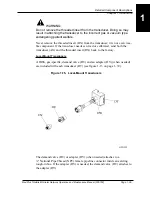
Local-Mount Transducers
A DISS, gas-specific, demand valve (DU) and an adapter (DV) (when needed)
are included with each transducer (DT) (see figure 1-15 on page 1–39).
Figure 1-15. Local-Mount Transducers
The demand valve (DU) or adapter (DV) (when needed) attaches to a
¼" National Pipe Thread (NPT) female pipeline connector inside an existing
rough-in box. If the adapter (DV) is needed, the demand valve (DU) attaches to
the adapter (DV).
MedPlus TotalAlert® Alarm Network Operation and Maintenance Manual (205728)
Page 1-39
Detailed Component Descriptions
Chapter 1: Introduction
1
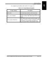
Summary of Contents for MedPlus TotalAlert
Page 370: ...Schematic Wiring Diagram Typical Local Alarm...
Page 371: ...Schematic Wiring Diagram Typical Master Alarm...
Page 372: ...Schematic Wiring Diagram Typical Master Alarm to Master Alarm...
Page 373: ...Schematic Wiring Diagram Typical Area Alarm...
Page 374: ...Schematic Wiring Diagram Typical Master Alarm to Three Area Alarm...
Page 375: ...Schematic Wiring Diagram Typical Master Alarm to Six Area Alarm Combination...


