


Page 4-20
MedPlus TotalAlert® Alarm Network Operation and Maintenance Manual (205728)
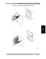
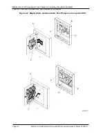
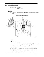
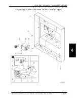
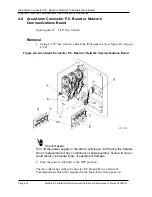
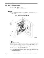
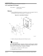
Master Alarm or Area Alarm Conversion Kit Power Supply
Chapter 4: Removal, Replacement, and Adjustment Procedures
Replacement
1. Install the two screws (H) securing the power supply assembly (C) to the
rough-in box (I).
2. Remove the two nuts (A) securing the high voltage cover (B) to the power
supply assembly (C).
3. Push out the knockout in the high voltage cover (B) where the box connector
(D) goes.
4. Install the box connector (D) in the knockout of the high voltage cover (B).
5. Push the input power wires (G) into the knockout in the high voltage cover
(B), ensuring that there is approximately 1" (25 mm) of sleeving (J) routed
through the box connector (D).
Shock Hazard:
Properly ground the MedPlus TotalAlert® Alarm Network Conversion Kit.
Failure to do so could cause personal injury or equipment damage.
6. Connect the input power wires (G) to the terminal block (F) in the following
order: line voltage to L, neutral to N, and ground to the earth ground symbol
(K).
7. Tighten the two screws (M) on the box connector (D) to secure the wiring.
8. Tighten the box connector (D) to secure it to the high voltage cover (B).
9. Connect the ground wire (E) to the terminal block (F).
10. Carefully route the ground wire (E) from the terminal block (F) through the
small opening (L) in the high voltage cover (B).
Shock Hazard:
Use care when installing the high voltage cover. Do not pinch or bind the
input power wiring or the ground wire. Personal injury or equipment dam-
age could occur.
11. Being careful not to pinch or bind any wiring, install the two nuts (A) to
secure the high voltage cover (B) to the power supply assembly (C).
12. Ensure that the power switch is in the ON position.
13. Close and lock the front panel door.
14. Turn on the power from the facility’s supply to the alarm, and to ensure prop-
er operation, perform the “Function Checks” on page 2–5.
Summary of Contents for MedPlus TotalAlert
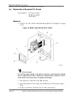
Page 370: ...Schematic Wiring Diagram Typical Local Alarm...
Page 371: ...Schematic Wiring Diagram Typical Master Alarm...
Page 372: ...Schematic Wiring Diagram Typical Master Alarm to Master Alarm...
Page 373: ...Schematic Wiring Diagram Typical Area Alarm...
Page 374: ...Schematic Wiring Diagram Typical Master Alarm to Three Area Alarm...
Page 375: ...Schematic Wiring Diagram Typical Master Alarm to Six Area Alarm Combination...


