


Page 1-22
MedPlus TotalAlert® Alarm Network Operation and Maintenance Manual (205728)
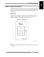
Detailed Component Descriptions
Chapter 1: Introduction
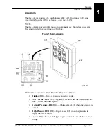
There are two dry-contact relays featured on the Master Alarm that provide sig-
nals to outputs. The outputs can be wired to either the normally-closed or nor-
mally-open contacts. They are located on the Master Alarm Breakout P.C. Board.
One is marked MAIN ALARM, and the other is marked AUX ALARM. For
wiring diagrams, refer to the foldouts at the rear of this manual.
• MAIN ALARM
•
When the Master Alarm is in alarm condition, this relay activates.
•
When the Master Alarm is silenced, this relay deactivates.
•
When the Master Alarm power is off, this relay activates until the power
comes back on.
• AUX ALARM
•
When the Master Alarm is in alarm condition, this relay activates.
•
When the Master Alarm is silenced, this relay stays activated.
•
When the Master Alarm condition is remedied, this relay deactivates.
The Master Alarm also has an output relay that can be used to interface with a
building automation system.
The Area Alarm has a relay output located on the Area Alarm Breakout P.C.
Board. It operates the same way as the AUX ALARM relay does on the Master
Alarm. For wiring diagrams, refer to the foldouts at the rear of this manual.
If the Network Communications Board is installed in the Area Alarm, the Master
Alarm can monitor the operation and condition of MedPlus TotalAlert® Area
Alarm Modules. Area Alarm Modules and transducers are programmed at the
factory with unique serial numbers and manufacturing dates. So the Master
Alarms can identify individual alarm components by using their unique serial
numbers.
The Master Alarm goes into an alarm condition when any one of the following
system or source alarms occur:
• Wiring to a sensor or switch is disconnected or interrupted.
• Alarm component fails and interrupts the system monitoring capability.
• If the Network Communications Board is installed in the Area Alarm, and the
Ethernet wiring is disconnected or interrupted.
• If the Network Communications Board is installed in the Area Alarm, and the
Area Display Modules or transducers have a fault.
Summary of Contents for MedPlus TotalAlert
Page 370: ...Schematic Wiring Diagram Typical Local Alarm...
Page 371: ...Schematic Wiring Diagram Typical Master Alarm...
Page 372: ...Schematic Wiring Diagram Typical Master Alarm to Master Alarm...
Page 373: ...Schematic Wiring Diagram Typical Area Alarm...
Page 374: ...Schematic Wiring Diagram Typical Master Alarm to Three Area Alarm...
Page 375: ...Schematic Wiring Diagram Typical Master Alarm to Six Area Alarm Combination...


