
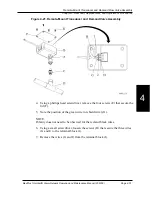
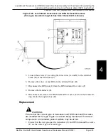

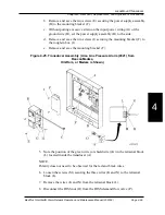


3. Using a phillips head screwdriver, remove the four screws (C) that secure the
lid (G).
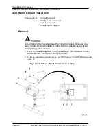
4. Note the position of the green wire (or shield wire) (E) in the terminal block
(F) located inside the transducer (B).
NOTE:
Polarity does not need to be observed for the red and black wires.
5. Using a small screwdriver, loosen the screws (J) that secure the three wires
(D and E) to the terminal block (F).
6. Remove the wires (D and E) from the terminal block (F).
Replacement
WARNING:
Ensure that the correct type of transducer and DISS demand flow valve is
installed for the type of gas or vacuum being monitored. If incorrect com-
ponents are installed, patient welfare may be at risk.
1. Ensure that the new gas-specific transducer is correct for the type of gas or
vacuum being replaced.
2. To replace the transducer, reverse the order of the removal instructions.
CAUTION:
Do not overtighten the DISS fittings. Equipment damage or inadequate
flow could occur.
3. Tighten DISS fittings until you feel resistance. They only need to be finger
tight.
4. Check for gas leaks, and repair if necessary.
5. To ensure proper operation, perform the “Function Checks” on page 2–5.
MedPlus TotalAlert® Alarm Network Operation and Maintenance Manual (205728)
Page 4-63
Remote-Mount Transducer
Chapter 4: Removal, Replacement, and Adjustment Procedures
4
Summary of Contents for MedPlus TotalAlert
Page 370: ...Schematic Wiring Diagram Typical Local Alarm...
Page 371: ...Schematic Wiring Diagram Typical Master Alarm...
Page 372: ...Schematic Wiring Diagram Typical Master Alarm to Master Alarm...
Page 373: ...Schematic Wiring Diagram Typical Area Alarm...
Page 374: ...Schematic Wiring Diagram Typical Master Alarm to Three Area Alarm...
Page 375: ...Schematic Wiring Diagram Typical Master Alarm to Six Area Alarm Combination...


