


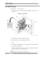


11. Using an 11/32" nut driver, tighten the two nuts (CK) that secure each of the
label holders (CG).
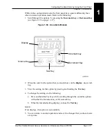
12. Turn the power switch (CJ) to the ON position.
13. Close the front panel (CI).
14. Using a 5/32" hex wrench, lock the front panel (CI).
15. For more information about installing an original alarm network, refer to the
MedPlus TotalAlert® Alarm Network Installation Instructions
.
16. For more information about installing a conversion kit alarm network, refer to
the
MedPlus TotalAlert® Alarm Network Conversion Kits Installation
Instructions
.
MedPlus TotalAlert® Alarm Network Operation and Maintenance Manual (205728)
Page 1-111
Area Alarm Labeling
Chapter 1: Introduction
1
Summary of Contents for MedPlus TotalAlert
Page 370: ...Schematic Wiring Diagram Typical Local Alarm...
Page 371: ...Schematic Wiring Diagram Typical Master Alarm...
Page 372: ...Schematic Wiring Diagram Typical Master Alarm to Master Alarm...
Page 373: ...Schematic Wiring Diagram Typical Area Alarm...
Page 374: ...Schematic Wiring Diagram Typical Master Alarm to Three Area Alarm...
Page 375: ...Schematic Wiring Diagram Typical Master Alarm to Six Area Alarm Combination...


