


Page 1-112
MedPlus TotalAlert® Alarm Network Operation and Maintenance Manual (205728)
Area Alarm Power-Up
Chapter 1: Introduction
Area Alarm Power-Up
Tools required:
5/32" hex wrench
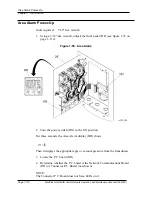
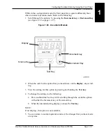
1. Using a 5/32" hex wrench, unlock the front panel (DF) (see figure 1-55 on
page 1–112).
Figure 1-55. Area Alarm
2. Turn the power switch (DG) to the ON position.
For three seconds, the Area Alarm display (BH) shows
init
.
Then it displays the appropriate gas or vacuum pressure from the transducers.
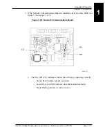
3. Locate the P.C. board (DH).
4. Determine whether the P.C. board is the Network Communications Board
(DH) or Connector P.C. Board (not shown).
NOTE:
The Connector P.C. Board does not have LEDs on it.
Summary of Contents for MedPlus TotalAlert
Page 370: ...Schematic Wiring Diagram Typical Local Alarm...
Page 371: ...Schematic Wiring Diagram Typical Master Alarm...
Page 372: ...Schematic Wiring Diagram Typical Master Alarm to Master Alarm...
Page 373: ...Schematic Wiring Diagram Typical Area Alarm...
Page 374: ...Schematic Wiring Diagram Typical Master Alarm to Three Area Alarm...
Page 375: ...Schematic Wiring Diagram Typical Master Alarm to Six Area Alarm Combination...


