

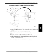
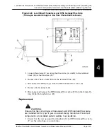

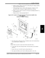


a. Install the two screws (J) securing the mounting bracket (G) to the rough-
in box (K).
b. Install the two screws (F) securing the power supply assembly (C) to the
mounting bracket (G).
c. Connect the two flag terminals (D) from the power supply assembly (C)
to the Area Alarm Breakout P.C. Board (E).
11. Turn on the incoming source power to the alarm.
12. Check for gas leaks.
13. If there are gas leaks, repeat step 2 through step 6 until no gas leaks occur.
14. To ensure proper operation, perform the “Function Checks” on page 2–5.
MedPlus TotalAlert® Alarm Network Operation and Maintenance Manual (205728)
Page 4-61
Local-Mount Transducer and DISS Demand Flow Valve Assembly for the Conversion Kit Housed in the
Area Line Pressure Alarm (0321) Rough-In Box
Chapter 4: Removal, Replacement, and Adjustment Procedures
4
Summary of Contents for MedPlus TotalAlert
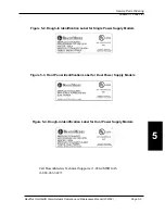
Page 370: ...Schematic Wiring Diagram Typical Local Alarm...
Page 371: ...Schematic Wiring Diagram Typical Master Alarm...
Page 372: ...Schematic Wiring Diagram Typical Master Alarm to Master Alarm...
Page 373: ...Schematic Wiring Diagram Typical Area Alarm...
Page 374: ...Schematic Wiring Diagram Typical Master Alarm to Three Area Alarm...
Page 375: ...Schematic Wiring Diagram Typical Master Alarm to Six Area Alarm Combination...


