


Control Wiring 5-3
MN765
5.2 Analog Inputs
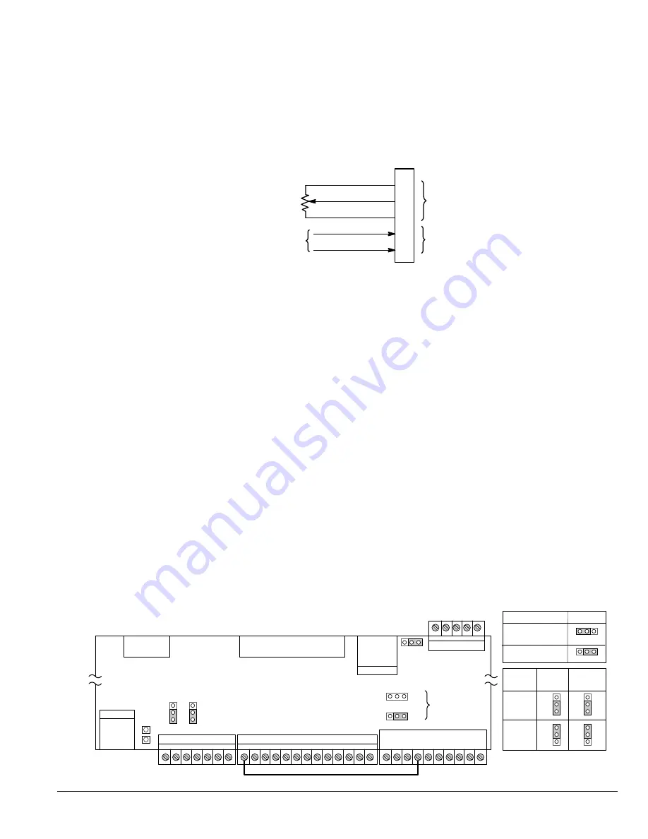
Two analog inputs are available: Analog Input 1 (J1-1 and J1-2) and Analog Input 2 (J1-4 and J1-5) as shown in Figure 5-2.
Either analog input may be selected in the Level 1 Input block, Command Source Parameter.
Figure 5-2 Analog Inputs
J1
Analog GND
Analog Input 1
Pot Reference
Analog Input +2
Analog Input -2
1
2
3
4
5
Analog Input 1
Analog Input 2
Command Pot or
0 - 10VDC
± 5VDC, ±10VDC,
0-20mA or 4-20mA Input
See recommended terminal tightening torques in Table A-2.
5.2.1 Analog Input 1 (Single Ended)
When using a potentiometer as the speed command, process feedback or setpoint source, the potentiometer should be
connected at Analog Input 1. When using Analog Input 1, the respective parameter must be set to “Analog Input 1”.
Note:
A potentiometer value of 5kΩ to 10kΩ, 0.5 watt may be used.
Parameter Selection
The single ended Analog Input 1 is typically used in one of three ways:
1. Speed or Torque command (Level 1 Input block, Command Source=Analog Input 1).
2. Process Feedback (Level 2 Process Control block, Process Feedback=Analog Input 1).
3. Setpoint Source (Level 2 Process Control block, Setpoint Source=Analog Input 1).
5.2.2 Analog Input 2 (Differential)
Analog Input 2 accepts a differential command ±5VDC, ±10VDC, 0-20 mA or 4-20 mA.
If pin J1-4 is positive with respect to pin 5 and P1408=±5V or ±10V, the motor will rotate in the forward direction.
If pin J1-4 is negative with respect to pin 5 and P1408=±5V or ±10V, the motor will rotate in the reverse direction. If forward
direction is not correct, change Level 2, Motor Data Reverse Rotation parameter P2415.
Analog Input 2 can be connected for single ended operation by connecting either of the differential terminals to common,
provided the common mode voltage range is not exceeded.
Analog Input 2 can be set for voltage or current mode operation. With JP1 as shown in Figure 5-3 , Voltage mode is
selected. If JP1 is connected to pins 2 and 3, current mode is selected.
The Level 1 Input Setup Parameter P1408 can be set to the full scale voltage or current range desired.
Note:
The common mode voltage can be measured with a voltmeter. Apply the maximum command voltage to Analog Input
2 (J1-4,5). Measure the AC and DC voltage across J1-1 to J1-4. Add the AC and DC values. Measure the AC and DC
voltage from J1-1 to J1-5. Add these AC and DC values. If either of these measurement totals exceeds a total of ±15
volts, then the common mode voltage range has been exceeded. To correct this condition, isolate the command
signal with a signal isolator, such as Baldor catalog number BC145.
Figure 5-3 Jumper Locations
Fault
USB
USB Port
J1
J2
J3
JP1
JP2
JP3
1
1
1
RS485
Keypad
Connector
Ribbon
Cable
Regen
Connector
Control
Circuit Board
JP6
JP5
P1
J7
J8
P2
P3
S G A B S
ENP
EPN
INP
DFT
Factory Settings
as shown
Note: Factory connection of
J2-8 (Enable) to J3-24.
24
8
See recommended tightening torques in Table A-2.
JP1
JP2
ANAIN2 ANAOUT1
Voltage
Current
1
1
1
1
Type
1
JP3
1
No Termination
120 ohm
Termination
RS485
Summary of Contents for VS1GV21-1B
Page 1: ...10 11 Installation Operating Manual MN765 VS1GV AC Closed Vector Control...
Page 12: ...2 2 General Information MN765...
Page 16: ...3 4 Installing the Drive MN765...
Page 78: ...6 16 Using the Keypad MN765...
Page 132: ...9 14 Troubleshooting MN765...
Page 172: ...A 16 Technical Specifications MN765...
Page 200: ...E 2 Remote Keypad Mounting Template MN765...
Page 201: ...Remote Keypad Mounting Template E 3 MN765...