AMF ES-505 Parts And Service Manual Download Page 47

ES-505

1-33

Released: 01/2018                                                                                                                                      

E-mail: [email protected]; webside: amfreece.com         

Phone: +420 582 309 146; Fax: +420 582 360 606

D - MACHINE CONTROLS
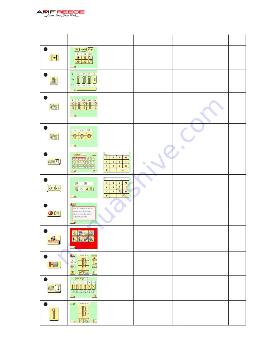
D 2.10.

D 2.5.

D 2.9.

7

9

9

10

11

12

Buttonhole sewing 

speed parameters

Number of stitches sewn slowly 

at the beginning of sewing

Sewing speed in the firs and 

second raw of stitches

Sewing speed in the eye

Sewing speed in the bar

Round buttonhole 

cutting parameters 

screen

Cutting types

Correction of cut in X / Y axes

Cutting time delay

Round buttonhole 

sewing speed screen

Error mesages screen

Current / following

screen

Button - 

icon

Screen name -

icon name

Parameter setting

Chapter

Counter mode

Total machine productivity

Standard cycling 

program screen

Error number

Error description

Instructions to eliminate errors

0

Cycling program from 1 to 47

Buttonhole program in chosen 

cycling program

D3.1.

D3.2.

D 5.1.

D 5.2.

13

14

Service menu screen

Setting machine parameters/

for traines service 

mechanics only

E2.1.

Productivity screen

Nuber of stitches sewn slowly at 

the end of sewing

Number of stitches sewn slowly 

at the beginning of sewing 

Round buttonhole sewing speed

Over-sewing speed

Number of stitches sewn slowly 

at the end of sewing

The main screen

Low battery alarm

15

16

Indexer cycle mode

screen

Number of cycle mode

Number of button hole

Distance between button hole

Button hole edit 

screen

Button hole parameters 

is possible to change according

describetion in section 

D2.1-D2.7

8

Electronic thread 

tension screen

(optional device)

Electronic thread tension 

D 2.8.

D 5.3.

D 4.1.

D 4.3.

Summary of Contents for ES-505

Page 1: ...ONHOLE MACHINE PARTS AND SERVICE MANUAL MACHINE SERIAL No PART NUMBER 97 1500 0 003 This manual is valid from the machine Serial No MODEL ES 505 R5050058 R5050059 R5050060 R5050061 AMF is trademark of...

Page 2: ......

Page 3: ...ONHOLE MACHINE PARTS AND SERVICE MANUAL MACHINE SERIAL No PART NUMBER 97 1500 0 003 This manual is valid from the machine Serial No MODEL ES 505 R5050058 R5050059 R5050060 R5050061 AMF is trademark of...

Page 4: ......

Page 5: ...AL 97 1500 0 003 ELECTRONIC EYELET BUTTONHOLE MACHINE PARTS AND SERVICE MANUAL 97 1500 0 003 ELECTRONIC EYELET BUTTONHOLE MACHINE PARTS AND SERVICE MANUAL 97 1500 0 003 ELECTRONIC EYELET BUTTONHOLE MA...

Page 6: ......

Page 7: ...caused by the use of non Genuine AMF Reece parts 6 Shipping or delivery charges There is no service labor warranty for machines sold as uninstalled Equipment installed without the assistance of a cert...

Page 8: ......

Page 9: ...on Customer s Name Customer s Mailing Address Customer s Telephone Number Supervising Mechanic s or Technician s Name Signature of Supervising Technician AMF Reece Technician s Name AMF Reece Technici...

Page 10: ......

Page 11: ...0 5 TECHNICAL CONDITIONS 1 11 5 1 BASIC MODEL 1 11 5 2 ULTRAFLEX MODEL 1 12 5 3 INDEXER MODEL 1 13 6 TERMINOLOGY USED TO DESCRIBE BUTTONHOLE PARTS 1 14 7 BUTTONHOLLE TYPES AND CUTTING OPTIONS 1 14 7 1...

Page 12: ...buttonhole sewing speed rde 1 50 3 CYCLE MODE 1 51 3 1 Selection of program number in standard cycle mode 1 51 3 2 Buttonhole program selection in cycle mode 1 52 3 3 Setting cycle mode with active op...

Page 13: ...20 UPPER THREAD TRIMMING MECHANISM AF LTT 1 93 21 BOTTOM THREAD AND GIMP TRIMMING LTT 1 94 22 LTT KNIFE REPLACEMENT 1 95 22 1 Replacing moving knife 1 95 22 2 Replacing fixed knife 1 95 23 KNIVES ADJ...

Page 14: ...60 606 1 2 1 Control box 1 111 1 2 2 Draining lubrication oil out 1 111 1 2 3 Eye safety cover 1 111 1 2 4 Lubrication 1 111 1 2 5 Battery replacement 1 112 2 MAINTENANCE LIST 1 113 3 MACHINE DISPOSAL...

Page 15: ...gle thread and optionally with gimp The machine is equipped with patented mechanisms to lower noise and vibration during high production Basic sewing parameters are set on the touch display using simp...

Page 16: ...Breaching procedures may cause functional problems with the machine 2 2 GENERAL SAFETY INSTRUCTIONS Before plugging the machine into electricity make sure that all covers are fitted Do not put the mac...

Page 17: ...power system it must be a type for devices with stray current and with high resistance to surge current in the operational conductor ie S type If there is a need to remove any of the safety covers sw...

Page 18: ...ES 505 1 4 Released 01 2018 E mail service amfreece cz webside amfreece com Phone 420 582 309 146 Fax 420 582 360 606 A INTRODUCTION 2 6 SAFETY AND INSTRUCTION LABELS ON THE MACHINE...

Page 19: ...ES 505 1 5 A INTRODUCTION Released 01 2018 E mail service amfreece cz webside amfreece com Phone 420 582 309 146 Fax 420 582 360 606...

Page 20: ...entofthemechanism whichwasdoneatthemanufacturer during assembly and final sew off After such interference into the mechanism new adjustmet of the mechanism and full inspection of the machine adjustmen...

Page 21: ...6 4 GENERAL MACHINE PARTS DESCRIPTION 4 1 BASIC MODEL 1 Sewing Head 2 Front Cover 3 Upper Cover 4 Rare Cover 5 Bed plate 6 Main Power Switch 7 Thread Stand 8 Foot Pedal 9 Eye Guard 10 Hand Wheel 11 Em...

Page 22: ...ULTRAFLEX a LTT Ultraflex LP1 Uses the range of sewing 13 30 mm It enables cutting only the buttonhole along its all length and also cutting only the eye section or partically the straight part of the...

Page 23: ...freece cz webside amfreece com Phone 420 582 309 146 Fax 420 582 360 606 4 2 2 Use of the machine 1 Slidding Block Mechanism 2 Motor 3 Sensor 4 Pressure changing valve 0 5 MPa 0 25 MPa 5 Regulator cut...

Page 24: ...thread chain stitch buttonholes on ready tailored jacket sleeves There is a thread catcher attached to the device which facilitates better quality of finished buttonholes b CT 14 26 I This model is de...

Page 25: ...ES 505 1 11 A INTRODUCTION Released 01 2018 E mail service amfreece cz webside amfreece com Phone 420 582 309 146 Fax 420 582 360 606 5 TECHNICAL CONDITIONS 5 1 BASIC MODEL...

Page 26: ...ES 505 1 12 Released 01 2018 E mail service amfreece cz webside amfreece com Phone 420 582 309 146 Fax 420 582 360 606 A INTRODUCTION 5 2 ULTRAFLEX MODEL...

Page 27: ...eans Fly Front A B C D Thread Catcher Yes Buttonhole Lenght 10 50 mm 14 26 mm Upper Thread Trimming Lower Thread and Gimp Thread Trimming short ends Range of LTT Angle Indexer Example for open end BH...

Page 28: ...2 Second raw of stitches 3 Eye area 4 Buttonhole end 5 Buttonhole cutting 6 Cutting space 7 Stitch bite 1 Number of stitches in eye 2 Stitch density 3 Eye width 4 Eye length 5 Total buttonhole lenght...

Page 29: ...Phone 420 582 309 146 Fax 420 582 360 606 7 2 ULTRAFLEX MODEL The table shows cutting options for buttonholes with and without eye with cross bar Both cutting options can be used for buttonholes with...

Page 30: ...146 Fax 420 582 360 606 A INTRODUCTION 8 SPECIAL ACCESSORIES 1 Working light 12 0008 4 875 2 Manual start control 03 5515 0 015 3 Pocket holder 03 5515 0 036 4 Thread nipper 03 5515 0 019 5 Optical s...

Page 31: ...st be reported to the freight forwarder immediately Check the content of the consignment with the order and inform the manufacturer on any discrepancies Later claims will not be taken into considerati...

Page 32: ...to various thickness table desk The threaded end of the bar 6 should not stick out the nut 5 for more than 1 mm 4 2 Once the ring is set 1 insert the washer 2 so that the slot is oriented towards the...

Page 33: ...freece com Phone 420 582 309 146 Fax 420 582 360 606 B MACHINE INSTALATION 5 CHECKING OIL TANK 5 1 To Cheb oil and to install drainage for excess oil use the tank 1 5 2 Screw the tankinto the bottom a...

Page 34: ...r and the machine does not start running The cutting cylinder is set to 0 5 MPa from the manufacturer with the screw 4 after loosing the nut 5 If the fabric is not cut correctly check the cutting bloc...

Page 35: ...e flat mat A good needle does not swing its tip when rolling 3 Tighten the screw 1 well 1 2 THREADING CAUTION Before you strat threading make sure the main switch is off The look and the quality of a...

Page 36: ...09 146 Fax 420 582 360 606 1 3 THREADING UPPER THREAD For threading see pictures below To make threading easier use threading tool 1 which is part of the machine accessories Threader 1 can be ordered...

Page 37: ...l CT Model LTT Model AF ES 505 1 23 Released 01 2018 E mail service amfreece cz webside amfreece com Phone 420 582 309 146 Fax 420 582 360 606 C PROPER USAGE 1 4 THREADING BOTTOM THREAD See pictures b...

Page 38: ...Model AF Model LTT CT ES 505 1 24 C PROPER USAGE Released 01 2018 E mail service amfreece cz webside amfreece com Phone 420 582 309 146 Fax 420 582 360 606 1 5 GIMP DRAW OFF See pictures below...

Page 39: ...2 1 FILLING UP OIL Before using the machine for the first time fill up oil tanks There are two lubrication circles in the machine one to run needle bar and bite second to drive sewing mechanism which...

Page 40: ...essary to check them every month Needle bar area Loosen screws 1 and remove front cover 2 Put a few drops of oil onto places marked with an arrow Once it is done put the cover back 2 and tighten the s...

Page 41: ...formation on manufacturer and numbers of programs downloaded into the machine Wait until the display shows main screen 3 3 3 If the main screen shows an error message in the field 4 the machine is not...

Page 42: ...e of the buttonhole from fabric edge Position of the screw 4 shows approximate distance of the buttonhole from the fabric edge Loosen the screws 4 and move the endstops 2 within 20 30 mm The distance...

Page 43: ...close the clamp feet They clamp the workpiece down Letting the pedal up brings clamp feet also up 5 4 Depressing the right foot pedal 2 starts sewing the shape of the buttonhole selected in the progr...

Page 44: ...ns 6 1 Press down the left pedal while sewing The machine stops and the display 1 changes screens 2 The workpiece is clamped down and held by the clamp feet the needle moves into the upper dead point...

Page 45: ...5 machine uses a universal program that enables various sewing of buttonholes just changing clamp plates Please make sure that the clamp plates in the machine correspond with the machine modification...

Page 46: ...h Number of stitches at the end of the second raw of stitches Stitch density Correction of position in X and Y axes Stitch bite Angle turning List of programs screen 6 6 Round buttonhole parameters sc...

Page 47: ...d cycling program screen Error number Error description Instructions to eliminate errors 0 Cycling program from 1 to 47 Buttonhole program in chosen cycling program D3 1 D3 2 D 5 1 D 5 2 13 14 Service...

Page 48: ...een without any change of parameters Pressing the button deletes all written letters and marks Pressing the button deletes the written letter or the mark Pressing the button saves set parameters and g...

Page 49: ...pace cycling mode The display in the service mode is protected with a password against unskilled settings Before starting programming for the first time it is necessary to enter a password to activate...

Page 50: ...fferent buttonhole sewing programs Programs 1 to 94 can be programmed as you like Programs 95 to 99 are set by the manufacturer and cannot be modified See chapter E1 of this manual for the list of tho...

Page 51: ...To make individual programs easier to find it is possible to save each program under a name A program name can have a combination of maximum 14 alphanumeric symbols Procedure Press the button 1 on the...

Page 52: ...thout eye with eye or round buttonhole If you press the button 3 buttonhole without eye is activated Pressing any of the buttons 4 indicates that the buttonhole with eye is active As you can see from...

Page 53: ...t eye with eye or round buttonhole buttons 2 Press the button 3 and the round buttonhole is highlighted active Press the button 4 and set the inner buttonhole diameter within the range 2 0 7 0 mm Pres...

Page 54: ...aw of stitches screen comes up Press the button 2 and set the buttonhole length it depends on machine type Press the button 3 and define the stitch density within the range 0 5 2 0 mm Press the button...

Page 55: ...es in the range of 5 at the end of the second raw of stitches 2 3 4 2 SETTING BUTTONHOLE FLY BAR Press the button 1 on the main screen The screen shows possible buttonhole ends Use buttons 2 to select...

Page 56: ...ition of the cross bar against the Y axis within the range 0 5 1 0 mm Press the button 7 and set the width of stitches within the range 0 5 mm Press the button 8 and adjust the position of the cross b...

Page 57: ...ss the button 1 on the main screen The screen shows possible buttonhole ends Use buttons 2 to select the required buttonhole end Press the button 3 which stand for the round end of an buttonhole with...

Page 58: ...een comes up Use this button 2 to select no cutting option Use this button 3 to select cutting before sewing CB Use this button 4 to select cutting after sewing CA Procedure Press the button 5 and cho...

Page 59: ...on 1 on the main screen of the round buttonhole The round buttonhole cutting screen comes up Select one of the options Use this button 2 for no cutting option Use this button 3 for cutting before sewi...

Page 60: ...2 2 Procedure Press the button 1 on the main screen The screen with buttonhole cutting parameters comes up Press the button 2 to select the Ultraflex cutting option The screen with Ultraflex cutting...

Page 61: ...within the range 0 22 mm for LP1 and LP2 The current cutting shape and cutting position is shown by the icon 10 Note Maximal values of set parameters depend on buttonhole length setup 2 6 3 Cutting th...

Page 62: ...one can sew individual buttonholes just like using the basic model Distance between indexer clamps is loaded after turn on the indexer The indexer activation sequence is the following Procedure Press...

Page 63: ...x 420 582 360 606 D MACHINE CONTROLS 2 8 SETTING ELECTRONIC THREAD TENSION Top thread tension value Bottom thread tension value First row of stitches Buttonhole eye Second row of stitches Bar tack for...

Page 64: ...and second raw of stitches within the range from 1000 to 2700 rtm Press the button 5 and set the speed in the eye within the range 1000 to 2700 rtm Press the button 6 and set the sewing speed for cros...

Page 65: ...es up Press the button 2 Numeric keyboard comes up Select a number of cycle program from 1 to 47 Selected cycle program number 4 comes up in the top part of the screen Confirm your choice with the but...

Page 66: ...chapters D 2 1 to 2 10 Procedure Press the button 2 Numeric keyboard comes up Select a required buttonhole program sewn at the position 1 Selected buttonhole program number is seen in the top part of...

Page 67: ...cycle mode being off The icon 2 shows the Ultraflex model and optical sensor being active To set cycle mode with active optical sensor follow the instructions Press the button 1 The cycle mode screen...

Page 68: ...nly no 1 button hole and no 2 lapel hole If sensor not active buttonhole no 1 button hole is sewn if sensor is active buttonhole no 2 lapel hole is sewn Activation or deactivation of the optical senso...

Page 69: ...t and from the right Select the initial side using button 2 Indexer angle info showed for Angle Indexer machine only Press button 3 to shift indexer by 1 position forward manually E g using this optio...

Page 70: ...t number of buttonhole at the subsequent positions those are to be sewn one after another in one cycle It is possible to select 6 different buttonholes Press the button 6 Numeric keyboard comes up Set...

Page 71: ...without saving 4 3 Buttonhole parameters changing Press the button 1 on main screen and select buttonhole you want to change parameters Screen with corresponding buttonhole comes up Change parameters...

Page 72: ...edited 5 1 1 SETTING DAILY CYCLE COUNTER Procedure Press the button 1 on the main green Productivity screen comes up Press the button 2 to delete the daily counter digit Press the button 3 Numeric ke...

Page 73: ...eck the connection of the battery or replace it with a new one The battery has to be replaced within 4 days otherwise data will get lost To replace the battery follow the chapter F 1 2 5 5 2 ERROR MES...

Page 74: ...cz webside amfreece com Phone 420 582 309 146 Fax 420 582 360 606 E STANDARD MACHINE ADJUSTMENT 1 STANDARD BUTTONHOLE SHAPES SET BY MANUFACTURER Programs 95 99 are pre programmed by the manufacturer...

Page 75: ...ng Only a skilled service mechanic may operate it Due to safety reasons the service menu is divided into several levels according to required specialty and frequency of usage Each level is sequred wit...

Page 76: ...t screen Servo drive and step motors testing Servo drive and step motors activation Testing all sensors icons pedals switching devices and motors functions E2 6 1 E2 6 2 Machine model and accessories...

Page 77: ...uency Instructions Press the button 1 on the main service screen Numeric keyboard comes up Enter number code for actual level see chapter E 2 2 1 Confirm with button 2 2 2 1 PASSWORDS AND PROTECTING L...

Page 78: ...tton program under a new program number Instructions Press the button 1 on the main screen Copy screen comes up Press the button 2 and numeric keyboard comes up Choose a program number that you like t...

Page 79: ...f the right pedal is active the display shows and the machine functions are operated by the left and right pedal Stepping on the left pedal activates feet and the workpiece is clamped and stretched St...

Page 80: ...g sequence depends on the parameter 4 If the left pedal is only active depress the left pedal If the right pedal is active as well see picture detail 4 Depress both pedals The bedplate moves once the...

Page 81: ...Model LTT model trimming all threads long tail of all threads 6 Thread catcher on off 7 Model RDE roun buttonhole Setting up models 15 CT 10 22 3 CT 14 26 4 CT 22 35 it is possible to change these par...

Page 82: ...en falls under the protection level III In case that the Ultraflex model is not being active on the main screen see icon 1 press button 2 to get in the service menu screen Press the button 3 and passw...

Page 83: ...s to activate the sensor from the main screen The screen falls under the protection level III Press the button 2 to get to service menu screen Once you press the button 3 password of the protective le...

Page 84: ...button 15 SQ5 Low air pressure 16 BQ13 Optical sensor at Ultraflex model only 17 BQ5 Home position of sliding cutting steel at Ultraflex model only 18 BQ10 Home position of indexer when sewing from t...

Page 85: ...s rotation of the race around the R axis Pressing the button 8 sets up the rotation speed of the race in R axis in the range of 2 310 rpm Pressing the button 9 activates the servo drive Pressing the b...

Page 86: ...push the button 1 The cutting lever cuts the fabric so many times how many times you push the button 1 Release the foot pedal MACHINE TYPE SETTING RANGE AF CT LTT 00 00 3F INDEXER 5F 40 7F INDEXER ANG...

Page 87: ...hine head Turn the hand wheel 3 in the arrow direction until the needle bar reaches upper dead point Loosen the screw 4 on the screen 5 and move it so that the match mark on the screen is in the centr...

Page 88: ...1 Loosen the screew 3 and set up the sensor plate 2 approximately to 10 mm from the console edge 4 Check the correct setting by bringing the machine into home position with pushing the button The dis...

Page 89: ...loopers support 3 towards the operator 7 2 Loosen the screw 5 in the pulley so that the screw 6 in the needle bar is on the left Set up the holder 4 of the needle bar side movement Tighten the screw...

Page 90: ...ck 7 Inserting the washer 2 heighten the support 1 direction B taking it out lowers it direction A Available thickness of washers 0 1 or 0 2 mm Use slide gauge to check the values 8 8 mm from upper ed...

Page 91: ...lamp feet 2 alongside in Y axis and sideways in X axis once screws 4 loosen 9 2 Set the feet 2 to overlap the plates 5 1 2 2 0 mm 9 3 Remove bedplate side covers 6 by unscrewing the screws 7 9 4 Place...

Page 92: ...foot separately Turning the screws 2 clockwise reduces the spreading Turning the screws anti clockwise extends it up to 1 8 mm at one clamp plate 10 2 Home position of mechanism levers 3 spread is ad...

Page 93: ...the cut to the sewn buttonhole adjust the position of the knife as in chapter D 2 4 to D 2 5 11 1 CHECKING CUTTING MECHANISM SETUP Make sure that the machine is in the home position Make sure that sel...

Page 94: ...bedplate move forward 11 1 5 Instead of fabric clamp in the machine a piece of paper see chapter C 4 11 1 6 Press the button and turn the hand wheel When the needle reaches upper dead point it pricks...

Page 95: ...olor and they cannot be loosen during the warranty period Knife 1 fixed in cutting block 2 has to be set up in correct position with the cutting steel 6 Loosen the screws 3 and with a gentle tapping m...

Page 96: ...tting lever into correct position Loosen the screws 2 and with a gentle tapping in X axis move the knife base 3 to the correct position Tighten the screws 2 Loosen the screw 5 Move the end stop 4 in Y...

Page 97: ...h the regulator 1 to 0 6 MPa Cutting knife pressure is preset by the manufacturer with the regulator 2 to 0 5 MPa Such pressure is suitable for all materials of up to 30 mm cut length For materials wi...

Page 98: ...rect knife print B Knife print i stoo deep C Different knife type caused two different prints D Partial knife print It is necessary to change the cutting knife or cutting steel if the cut length is ch...

Page 99: ...w 1 and move the sensor 2 in required direction as in the picture Tighten the screw 2 to secure the position of the sensor 1 Check the correct adjustment by repeated pressing of Immediate cutting acti...

Page 100: ...side amfreece com Phone 420 582 309 146 Fax 420 582 360 606 E STANDARD MACHINE ADJUSTMENT 13 STANDARD SEWING CAM SETTING Bring the needle bar into home position Loosen the screw 3 Turn the cam 1 as ne...

Page 101: ...that the left and right loop strokes are the same 14 1 Remove the two screws 1 an then remove the needle bar guard 2 14 2 Turn the upper shaft pulley 3 to set the needle bar to its lowest position at...

Page 102: ...measure the lenght from the edge of the bar 2 to the top of the needle bar bush holder base 3 15 3 Add 3 5 mm to the value obtained in step 2 above and set the width with the calipers to the resulting...

Page 103: ...p edge of the needle hole in the needle center 2 when the needle is at the inside sewing position 16 3 Loosen the two screws 4 of the top and bottom needle bar clamps 3 16 4 Lower the needle bar 5 1 5...

Page 104: ...he same steps to to adjust right looper 4 by loosening the screw 5 so that the gap along the needle when the looper passes by the needle is the same 0 1 0 2 mm Secure the position by tightening the sc...

Page 105: ...and 4 It must be as small as possible Right looper 0 05 mm max so that sewing thread cannot go between right looper 5 and spreader 3 Left looper 0 1 mm min so that sewing thread can go between left lo...

Page 106: ...lly unscrew the screws on the upper cover at first and remove the upper cover 19 1 Loosen the screw 1 and the securing screw 2 and loosen the nut 3 19 2 When adjusting the bite to smaller one 1 9 mm m...

Page 107: ...crews 5 The knife edge must be 0 9 mm from the needle 8 When the position of the knife is changed it is necessary to check the height to keep the play as in 20 1 20 3 Adjust the home trimming knife an...

Page 108: ...p and at the bottom with the guiding plates 1 21 2 The leaf springs 3 bottom thread and 4 gimp hold correct position of the bottom thread and the gimp is ensured by the grasping fixing plate 2 21 3 Lo...

Page 109: ...10 and remove the thread separator 11 Put the new moving knife 4 Install a new thread divider 11 onto a new moving knife 4 and screw the screws 10 Then fit a new moving knife 4 on the moving knife lev...

Page 110: ...here was no play between them Adjust the top knife edge 6 so that it is flat with the knife 7 23 3 Align the springs 18 and 17 with the knife 6 spring offset 16 is on the site facing the knife 6 Tight...

Page 111: ...nt 6 the mark on the knife 7 Tighten the screws 24 24 1 BOTTOM THREAD HOLDER OPENER Turn the moving knife 7 in A direction so that the knife front 6 matches the knife edge 7 In this position the threa...

Page 112: ...pper in the home position 25 2 Set up the play 0 5 mm between the nut 1 and the nipper holde 2 25 3 When the nipper pneumatic cylinder 5 is moved out adjust the distance between the nipper arms 6 and...

Page 113: ...must lean against the front side of the throat plate 3 so that it catches and holds the bottom thread for another button hole During the trimming knife 1 movement the thread catcher 13 must go throug...

Page 114: ...e the upper knife 6 and lower knife 7 Install new knives and put the screw 4 with the washer 5 back Adjust the cutting pressure as in chapter E 26 2 and then tighten the screw 3 Put the knife upper co...

Page 115: ...rimming on the free thread If the trimming is not sufficient reduce the gauge from 3 8 mm to 3 5 mm The scissors must move freely The edge must not be damaged with scratches If the scissors do not cut...

Page 116: ...100 579 Nm 100 Upper thread tension N 1 2 1 7 2 Bottom thread tension N 0 2 0 7 1 7 Turn the tensioner nut 1 clockwise to increase the upper thread tension and anticlockwise to reduce it Turn the auxi...

Page 117: ...309 146 Fax 420 582 360 606 E STANDARD MACHINE ADJUSTMENT 29 2 BOTTOM THREAD Turn the tensioner nut 1 clockwise to increase the bottom thread tension and anticlockwise to reduce it For CT and LTT ver...

Page 118: ...TION Tension tight too much in the tensioner can cause deformation of a buttonhole in the eye It is not necessary to adjust any bottom thread tension at AF versions CT and LTT versions need to have gi...

Page 119: ...ose clamp holders screws 1 on the left and right side of the Indexer 1 2 Set up a gap of 0 5 0 7 mm between feet 2 and desktop cover 3 feeler gauge can be used 1 3 Verify the setting by pressing the b...

Page 120: ...necessary to hold the minimal play 2 1 Check whether the play on the machine is set on to 2mm in both positions of the Indexer Use this display buttons to make a move 2 2 If the 2 mm distance is not...

Page 121: ...LAMPING FEET Change the distance between clamping feet 1 if you want to change workpiece or number of buttonholes to be sewn 3 1 Loose the screws 2 of the right holder 3 and move the holder 3 to the l...

Page 122: ...between Indexer feet and clamping mat of the sewing head see chapter 2 X 4 1 x 25 2 77 mm Minimal distance must be adjusted to 77 mm If the minimal distance is shorter the display signals an error mes...

Page 123: ...sconnect the air supply from the machine 1 1 DAILY CLEANING AND CHECKING To ensure machine long life and reliability it is important to apply below mentioned steps on daily bases after work shift 1 1...

Page 124: ...r sleeve 3 Filter sleeve must be changed after two years of machine operation at the latest or every time the pressure drops down to 0 1MPa How to exchange filter sleeve c Push latch 6 in the directio...

Page 125: ...Draining lubrication oil out Check the oil tank 1 under the machine If it is full of oil remove the tank by turning it clockwise and used oil empty out Put the tank back onto its place NOTE Disposal o...

Page 126: ...f the machine stays switched on When replacing the battery make sure you do the following a Never shorten the connector from the battery in the PLC Never charge the battery Never break the battery All...

Page 127: ...ilth in filter sleeves in control box Check tank and waste oil Check screw joints tightness keep values below Recommended values for screws freeze Nm M3 0 5 0 6 0 8 M4 1 2 1 5 2 0 M5 2 5 3 0 4 0 M6 4...

Page 128: ...ES 505 1 114 Released 01 2018 E mail service amfreece cz webside amfreece com Phone 420 582 309 146 Fax 420 582 360 606 H DOCUMENTATION 1 PNEUMATIC DIAGRAM...

Page 129: ...ES 505 1 115 Released 01 2018 E mail service amfreece cz webside amfreece com Phone 420 582 309 146 Fax 420 582 360 606 H DOCUMENTATION 2 ELECTRICAL DIAGRAM...

Page 130: ......

Page 131: ...on display 2 3 1 2 List of values to set up mechanisms 2 4 2 FAILURES NOT INDICATED BY ERROR MESSAGE 2 4 3 ELECTRICAL FAILURES 2 7 3 1 FAULTS INDICATED ON DISPLAY BY ERROR MESSAGES 2 7 3 2 FAULTS THAT...

Page 132: ......

Page 133: ...sition Error 07 Not used Error 08 Machine opened close machine Error 10 S axis faulty not in home position Error 11 X axis faulty not in home position Error 12 Y axis faulty not in home position Error...

Page 134: ...l play of needle bar in the bottom dead point with 5N force is 0 05mm 0 002 inch loopers holder axial play 0 05 0 1mm 0 002 0 004 inch loopers holder radial play 0 05 0 1mm 0 002 0 004 inch loopers ho...

Page 135: ...eck the needle and replace with new one if necessary C 1 G 1 1 2 Needle and loopers adjustment incorrect Check adjustment of needle loopers needle bar height or spreaders C 1 G 1 1 2 Incorrect clearan...

Page 136: ...r CT E 23 E 21 Clearance between loopers and left spreader adjusted incorrectly Check spreaders and loopers clearance E 15 E 16 Material is improperly cut Cutting pressure is too low Adjust pressure o...

Page 137: ...ng is not adjusted Adjust contact making of SA2 switch The switch has to make contact once the machine is closed 3 Faulty switch SA2 Check or replace switch SA2 06 0120 0 000 4 Faulty input PLC A 0 10...

Page 138: ...up error not indicated still servo driver does work correctly 1 Not efficient connection of connector CN1 and cable with servo amplifier Check correct connection connection of all servo amplifier conn...

Page 139: ...ing on all communication block 2 Faulty cable between PLCs Repair replace 06 1500 0 052 3 Faulty communication block on PLC Replace block 12 0010 4 067 3 2 FAULTS THAT SHOWS ONCE MACHINE IS STARTED Fa...

Page 140: ...version for your machine Once the machine is switched on with the power switch the display is illuminated but it does not show correct information 1 Display communication cable disconnected Check corr...

Page 141: ...hine is switched on with the power switch discharged battery icon is appeal on main green 1 Faulty battery connection Check battery connection 2 Battery is discharged Change the battery chap G 1 2 5 1...

Page 142: ...r PLC extension box See input output table and match valve with PLC output and check circuit continuity PLC outputs yellow color cable When output activated by pressing relevant button on output test...

Page 143: ...cable no 51 blue pol to connection box X1 Scanning sensor indicator light is on after manual move but tests on display do not show indication 1 Connector X7 or X8 on power line disconnected Check cor...

Page 144: ...cted from driver Axes motor does not drive onto its sensor it does not move even though no error on drive is signaled 1 Motor keeps its position cannot be moved manually but it does not get signal to...

Page 145: ...air valve J1 see description of air valve function faults After pressing left foot pedal machine lowers down clamp feet and starts sewing immediately does not wait for second pedal to be pressed down...

Page 146: ......

Reviews: