background image


CP-3000 User’s Guide 

3-7


Step 7

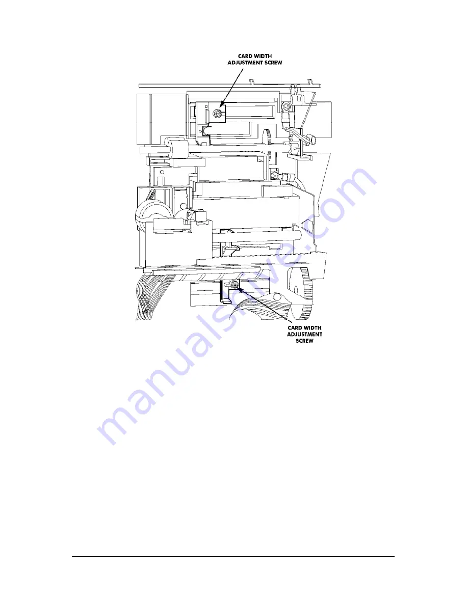
Loosen the lower card width adjustment screw, insert the card 
into the card throat and slide the guide to adjust the width 
allowing 0.0197” (0.5 mm) between the card and the guide. 
Tighten the screw.  

Step 8

Reconnect the battery.  

Step 9

Install the front cover.  

Step 10

Reconnect the power cord to the power source. 

Step 11

Program the correct time and date. 

Step 12

Set the 

Mode Switch 

to 

NORMAL 

and install the top cover.  


Summary of Contents for CP-3000

Page 1: ...CP 3000 Electronic Time Recorder User s Guide ...

Page 2: ...provements which may not be reflected in this document Portions of this document may have been updated to include the latest hardware or firmware version if applicable To ensure safe use of this time recorder stamp be sure to thoroughly read this manual in its entirety before any attempt is made to operate the equipment After you have finished reading this manual be sure to store it and in a safe ...

Page 3: ...7 Initialization and Reset 2 9 Initialization 2 9 Reset All Clear 2 10 Power Connection 2 10 Chapter 3 Time Cards 3 1 Making a Test Print 3 1 Card Dimensions 3 2 Card Color 3 3 Time Card Settings 3 3 Card Thickness Adjustment 3 5 Card Width Adjustment 3 6 Chapter 4 Programming 4 1 Introduction 4 1 General Programming Guidelines 4 1 Entering Program Mode 4 1 Entering and Saving Values 4 2 Scrolling...

Page 4: ...ing Weekly Programs 4 20 Adding Additional Weekly Programs 4 21 Deleting a Weekly Program 4 21 Chapter 5 Maintenance 5 1 Service 5 1 Exterior 5 1 Fuse Replacement 5 1 Ribbon Replacement 5 2 Chapter 6 Troubleshooting 6 1 Introduction 6 1 General Problems 6 1 Signal 1 6 1 Foreign Object or Material 6 2 Programming 6 2 Key Failure 6 2 Audible Beeps 6 2 Error Messages 6 3 Err 0 thru Err 5 6 3 Leap Yea...

Page 5: ...8 Card Feed Problems 6 8 Card Refused 6 8 Card Cannot Enter or Card Blocked 6 9 Card Refused Date and Time in Display 6 9 Imprint Problems 6 9 Overprint 6 9 Imprint Position Wrong 6 10 Wrong Color Printed 6 10 Weak or Light Printing 6 11 Diagnostics 6 11 LED Test 6 12 Mode and Keys Test 6 12 LCD Test 6 13 EPROM Test 6 14 Buzzer Test 6 14 Signal 1 Test 6 15 Color Change Test 6 15 Model ID 6 16 Chap...

Page 6: ...iv CP 3000 User s Guide This page intentionally left blank ...

Page 7: ...Power 120 VAC 10 50 60 Hz Power Consumption 6 W Idle 60W maximum Ambient Temperature 14 F to 113 F 10 C to 45 C Ambient Humidity 10 to 90 non condensing Dimensions 5 9 150 mm Wide X 6 9 175 mm High X 6 0 152 mm Deep Weight Approximately 4 85 lbs 2 2 kg Environment Indoor use only dust free environment Keep out of direct sunlight Time Card Electronically configured for 3 375 86 mm wide Clipper type...

Page 8: ...ote that specifications appearance and or description are subject to change without notice due to product enhancements This user s guide has been carefully prepared but Amano assumes no liability for errors and or omissions If you should find any errors or unclear information please contact your Amano dealer Names and Functions of Parts The following describes the names and functions of various pa...

Page 9: ...g table Features A050 A051 A056 Single Color Printing X Two Color Printing X X Signal Device X X Full Power Reserve X X X Index No Imprint X Front Panel Description The front panel displays the date time day of the week and is used for programming the unit It is accessed by removing the top cover see Chapter 2 Getting Started for more details ...

Page 10: ...1 4 CP 3000 User s Guide Note ESD Electrostatic Discharge precautions should be adhered to before touching the Mode Switch ...

Page 11: ...ttery Connection Intialization and Reset and Power Connection Top Cover The top cover must be removed to configure install and program the CP 3000 To remove the top cover follow these steps Step 1 Insert the key provided in the keyhole and turn the key clockwise to unlock the cover The top cover should pop open Step 2 Pivot the top cover upwards and lift the cover to remove Step 3 To re install th...

Page 12: ...s in the upper corners of the housing Step 5 Press both of your hands flat against the sides of the front cover Step 6 Pivot the front cover towards you and remove Set face up on a flat surface Installation Step 1 With the front cover on a flat surface and facing up press both of your hands flat against the sides Step 2 Facing the bottom of the unit set and align the tabs on the bottom of the fron...

Page 13: ...of supporting the unit s weight 9 66 lbs 4 38 kg The area must be within the specified operating temperature range The unit is close to a power source or wall outlet The area can accommodate signal and or power conduits The following conditions do not exist Desktop Installation Place the time recorder on a level surface The recommended height of the surface should be 29 75 cm from the floor ...

Page 14: ... final locationof the clock and mark the location of the teardrop mounting hole on the wall Step 6 Hang the back plate on a screw or anchor from the teardropmounting hole Step 7 Level the back plate and mark the location of the bottom twomounting holes Step 8 Secure the back plate to the wall by inserting screws through thebottom two mounting holes Step 9 Holding the sides of the cover lift the CP...

Page 15: ...odel A051 and A056 versions of the CP 3000 are equipped with a single external signal relay circuit that enables you to activate an audible device such as a bell or buzzer The relay contacts of the circuit are Normally Open and should not exceed Class 2 Circuit requirements 30 VAC RMS at 3A or 30 VDC at 3A It is recommended that a Surge Absorber Amano P N ESA 100010 be connected as shown to elimin...

Page 16: ...ernal device connect the signal wires to it and run them to the mounting location of the CP 3000 Make sure the wires are properly labeled Step 3 Strip approximately 0 25 6 35 mm of insulation off the ends of the wires that will be connected to the CP 3000 Step 4 Remove the top cover from the CP 3000 Step 5 Remove the front cover Step 6 With the unit flat and face up locate terminal block CN7A CN7B...

Page 17: ...ation Step 10 Check the connections by tugging on each wire If they appearloose repeat the previous step Step 11 Clamp the signal wires as shown in the following drawing using a cable clamp appropriate toyour cable thickness Connecting the Battery The CP 3000 is equipped with a Full Power Reserve Battery that will maintain normal operations for 72 hours or 300 punches in the event of an AC power f...

Page 18: ...e chassis Step 4 Connect the battery cable to CN13 on the PC Board If the battery is properly connected the following will occur the LCD will display the default time in the As Shipped 12 hour format an LED indicator will blink and the ribbon carriage will cycle Step 5 Replace the front cover Step 6 Replace the top cover Note The As Shipped time display format setting is configured at the factory ...

Page 19: ...ation The power reserve battery is intended to be used for limited power outages not as a power source during normal operations Initialization and Reset Initialization Prior to first use the CP 3000 must be initialized Initialization resets the time and date to their default settings but does not affect their As Shipped format Note This procedure must be performed with the power cord disconnected ...

Page 20: ...ly reset your CP 3000 when prescribed to in the Troubleshooting section of this manual Note ESD Electrostatic Discharge precautions should be adhered to before touching the Mode Switch To Reset Clear All your CP 3000 perform the following Step 1 Set the Mode Switch to PROGRAM Step 2 Insert a small screwdriver into the Reset Hole on the bottom of the unit and press and hold the Reset button Step 3 ...

Page 21: ...er is connected Please refer to the Basic Programming section of Chapter 4 to set the year time date and the hours display format Note The battery is fully charged prior to shipping however to insure premium performance it is recommended that the battery be fully recharged prior to use approximately 24 hours Note To avoid damaging the battery or draining it to an unrecoverable level keep the machi...

Page 22: ...2 12 CP 3000 User s Guide This page intentionally left blank ...

Page 23: ...een ejected Step 3 As shipped the CP 3000 is configured to print the following imprint Step 4 If this imprint is acceptable and is correctly positioned on your time card the CP 3000 is ready to be programmed for use time and date If time card adjustments must be made refer to the following sections in this chapter If you wish to change the style of the imprint you must program an imprint style for...

Page 24: ...he recommended column dimensions are as follows where Bm Bottom Margin 0 827 21 mm from bottom of time card Sm Side Margin 0 276 7 mm from left edge of time card Imprint Length 1 734 44 mm The CP 3000 allows you the flexibility to modify the time card dimensions if your application requires it The Bottom and Side Margins of the imprint are adjusted in the Program Mode The time card width and thick...

Page 25: ...h and location of the imprint should be taken into consideration Since the CP 3000 uses the Column Position Block on the imprint to record column position the imprint can not be aligned with any corresponding lines or artwork in the card If this occurs the card will be ejected and a beep will sound Card Type Setting The only allowable Card Type Setting for the CP 3000 is 18 This setting correspond...

Page 26: ...Adjustment Step 1 If you have not already done so enter theProgram Mode and press the FUNCTION key until the Time Card menu item appears in the display Step 2 Press the NO key to select the Side Margin Adjustment Password of 8 Step 3 When the correct value appears in thedisplay press the YES key A password confirmation display will appear If the value in the display is correct press the YES button...

Page 27: ...value appears press the YES key Step 5 Exit the Program Mode and insert a time card into the card throat to test Note This feature is only for small variations Card Thickness Adjustment The CP 3000 is factory set for a time card thickness of 0 0126 0 32 mm It can be adjusted for time cards with a thickness of 0 0079 to 0 0197 0 2 mm to 0 5 mm To set the card thickness perform the following steps S...

Page 28: ...3 375 86 mm wide card The width can be adjusted from 2 6004 to 4 2158 66 mm to 107 mm Follow these steps to adjust the width Step 1 Disconnect the power cord from the power source Step 2 Remove the top cover Step 3 Set the Mode Switch to program Step 4 Remove the front case Step 5 Disconnect the battery Step 6 Loosen the upper card width adjustment screw insert the card into the card throat and sl...

Page 29: ...de the guide to adjust the width allowing 0 0197 0 5 mm between the card and the guide Tighten the screw Step 8 Reconnect the battery Step 9 Install the front cover Step 10 Reconnect the power cord to the power source Step 11 Program the correct time and date Step 12 Set the Mode Switch to NORMAL and install the top cover ...

Page 30: ...3 8 CP 3000 User s Guide This page intentionally left blank ...

Page 31: ...ming consists of activating specific features of the CP 3000 such as the built in buzzer relay signal contacts ribbon color two color only at predetermined times of the day and on specific days of the week General Programming Guidelines Entering Program Mode Note ESD precautions should be adhered to before touching the Mode Switch To enter the Program Mode remove the top cover and set the Mode Swi...

Page 32: ...ee seconds To save values entered press the YES key Some menus and items require that the entire sequence be cycled through before saving the values entered Scrolling Through the Program Mode While in the Program Mode press the FUNCTION key to advance to the next menu position An LED indicator will light for each menu position Continue pressing the FUNCTION key and the cursor will eventually retur...

Page 33: ...CP 3000 User s Guide 4 3 Programming Guides The following is a reference guide for programming the Model A050 and Model A051 versions of the CP 3000 Chart continued on next page ...

Page 34: ...4 4 CP 3000 User s Guide Note The As Shipped imprint settings are configured at the factory If the CP 3000 should lose its configuration it will revert to the default imprint settings ...

Page 35: ...CP 3000 User s Guide 4 5 The following is a reference guide for programming the Model A056 version of the CP 3000 Chart continued on next page ...

Page 36: ...4 6 CP 3000 User s Guide Note The As Shipped imprint settings are configured at the factory If the CP 3000 should lose its configuration it will revert to the default imprint settings ...

Page 37: ...n Step 3 When the correct year appears press the YES key The display will automatically move to the Month and Date menu item The first pair of digits month will flash in the display Step 4 Press the NO key until the correct month number 01 thru 12 appears in the display then press the YES key Step 5 The next set of digits the Date of the Month will flash in the display Step 6 Press the NO key unti...

Page 38: ...ours Display menu item Step 1 Set the Mode Switch to the PROGRAM position if you have not already done so The Year menu item will automatically appear in the display Step 2 If applicable press the YES key until the Hours and Minutes menu item appears in the display with the first pair of digits hour flashing Step 3 Press the NO key until the correct hour in 24 hour format 00 thru 23 is flashing in...

Page 39: ...press the FUNCTION key before saving Step 1 If you have not already done so enter theProgram Mode and press the FUNCTION key until the Day Change Time menu item appears with the first pair of digits hour flashing in the display Step 2 Verify that 00 is flashing in the display and press the YES key The second pair of digits minutes will begin to flash Step 3 Verify that 00 is flashing in the displa...

Page 40: ...gh the sequence of displays of each item and save the data entered The data entered will not be saved if you exit the Program Mode or press the FUNCTION key before saving By Week Number Step 1 If you have not already done so enter theProgram Mode and press the FUNCTION key until the Day Change Time menu item appears in the display Step 2 Press the YES key three times until the DST Begin Date menu ...

Page 41: ...o edit these settings press the NO key This will return you to the display described in step 4 To save these settings press the YES key When saved the display will move to the Time Card Settings menu Step 7 Exit the Program Mode by setting the Mode Switch to NORMAL By Month and Day Step 1 If you have not already done so enter theProgram Mode and press the FUNCTION key until the Day Change Time men...

Page 42: ... the correct month 01 thru 12 appears in the display Holding down the NO key for more than three seconds will increment the number in the display by ten To edit these settings press the NO key To save these settings press the YES key When saved the the second pair of digits date will flash in the display Step 7 Press the NO key until the correct date 01 thru 31 appears in the display Holding down ...

Page 43: ...ollowing steps Step 1 Enter the Program Mode and press the FUNCTION key until the Hours Display menu item appears in the display Step 2 Press the NO key to select a value of 1 for 24 hour time format or 2 for 12 hour time format Step 3 When the desired value appears press the YES key The display will automatically move to the Hour Imprint menu item Step 4 Press the NO key to select a value of 1 fo...

Page 44: ...for the Index No Imprint to appear on the time card Step 9 When the desired value appears press the YES key The display will automatically move to the Year Imprint menu item Step 10 Press the NO key to select a value of 0 for no year imprint OFF or 1 to include the year in the imprint ON Step 11 When the desired value appears press theYES key The display will automatically move to the Month Imprin...

Page 45: ...me cards using an Index No Imprint numbered 00 thru 99 Note The Day Imprint must have a value of 9 for the Index No Imprint to appear on the time card Step 1 Enter the Program Mode and press the FUNCTION key until the Index No Imprint menu item appears in the display Step 2 Press the NO key to select a value of 00 thru 99 that will be used to identify this time clock on a time card Step 3 When the...

Page 46: ...he display should be zero If it is not press the NO key until zero appears in the display then press the YES key Step 5 Exit the Program Mode by setting the Mode Switch to NORMAL Weekly Programming This menu allows you to create a weekly schedule that will enable or disable certain features of the CP 3000 at predetermined times of the day and on specific days of the week This schedule is comprised...

Page 47: ...Monday flashing in the display Step 2 Press the NO key to deselect omit days of the week from the schedule or press the YES key to select include days of the week on the schedule Days that the schedule will operate on will be shown in the display as cursors Step 3 When the days of the week are selected the display will flash the hour of the selected days that the schedule will be activated Note Al...

Page 48: ...the Signal Duration menu item Step 7 Press the NO key to enter a value of 0 to disable OFF or 1 For Model A051 and A056 only to enable ON Signal 1 When the correct value appears in the display press the YES key The display will move to the next object Signal 2 Step 8 This menu item is used for verification only The value in the display should be zero If it is not press the NO key until zero appear...

Page 49: ...program number Step 11 Repeat the previous steps to enter in the next program As a convenience Obtaining a Printout of Programmed Data Step 1 If you have not already done so enter the Program Mode and press the FUNCTION key until the Program Printout menu item appears in the display The default value of this item is zero or OFF Step 2 Press the NO key to change the value in the display to 1 or ON ...

Page 50: ...will automatically move tothe next menu Exit the Program Mode by setting the Mode Switch to NORMAL Editing Weekly Programs Step 1 Obtain a printout of the current Weekly Programs Step 2 Mark on the printout the desired Weekly Program that you want to change Step 3 Enter the Program Mode and press the FUNCTION key until the Weekly Program menu item appears in the display Step 4 Press and hold the Y...

Page 51: ...e to the Program Printout menu item and print out a copy of the program to check Deleting a Weekly Program Step 1 Obtain a printout of the current Weekly Programs Step 2 Mark on the printout the desired Weekly Program that you want to delete Step 3 Enter the Program Mode and press the FUNCTION key until the Weekly Program menu item appears in the display Step 4 Press and hold the YES key until the...

Page 52: ...4 22 CP 3000 User s Guide Step 8 After saving the program press the FUNCTION key to move to the Program Printout menu item and print out a copy of the program to check ...

Page 53: ...eplacement There are two fuses used in the CP 3000 The main fuse is a 250 V F2A Fast Acting fuse The second fuse which protects the power supply is a 250 V F4A Fast Acting fuse To replace either fuse perform the following Step 1 Disconnect the power cord from the power source Step 2 Remove the top cover and the front cover Step 3 Disconnect the battery Step 4 Lift up the insulator flap and locate ...

Page 54: ...ty prints and ink residue on print head rollers and the time card Note Extreme care should be used when removing the ribbon Verify that the Mode Switch is set to PROGRAM before attempting to remove the ribbon Forcing the ribbon out of the ribbon carriage may damage the ribbon guide Perform the following steps to replace the ribbon Step 1 Remove the top cover Step 2 Set the Mode Switch to PROGRAM S...

Page 55: ...clicks into place Turn the knob clockwise to remove any slack in the ribbon Step 7 Rotate the front panel down until it clicks in place Step 8 Set the Mode Switch to NORMAL Step 9 Insert a time card into the card throat to check the printing qualityand to confirm that you have installed the ribbon properly Step 10 Replace the top cover ...

Page 56: ...5 4 CP 3000 User s Guide This page intentionally left blank ...

Page 57: ...it Perform a Reset Clear All to reset the unit to defaults If after performing the above you still are unable to resolve the problem or feel that your unit requires servicing contact your local Amano dealer General Problems Signal 1 If you are experiencing a problem with the relay signal circuit Model A051 and A056 only you should perform the following Verify that the connections to CN7A CN7B are ...

Page 58: ...tery and remove the foreign objects Programming If you suspect a programming problem or the imprint position margin is incorrect it is recommended that you obtain a printout of the programmed information as described in Chapter 4 and troubleshoot the programmed data or perform a Reset Clear All to reset the unit to defaults If you are unable to resolve the problem please contact your local Amano d...

Page 59: ...iate attention Leap Year Error February 29th is programmed for a non leap year If this occurs the date will automatically be changed to March 1st of that year Please check your programmed year month and date This message can also be cleared by performing a Reset Clear All Printing or Ribbon Error The time card sensors could not detect the Column Position Block Possible reasons are The imprint qual...

Page 60: ...h The time card you are using is too narrow for the imprint Remove characters from the imprint or use a wider card There is dirt oil dust or ink residue on the surface of the time card or the time card surface is too rough for the time card sensor to detect the Column Position Block Replace the card The background color of the time card is too dark Time Card Error When this message is displayed pr...

Page 61: ...accept new cards beep and may display the following error message If this occurs please take the time card out of the card throat and wait for several minutes Err 6 thru Err 9 These error messages will remain in the display until the problem is resolved and the CP 3000 is restarted by pressing any key with the message in the display When displayed the time and date will be maintained unless your A...

Page 62: ...ge the battery by allowing the unit to be connected to AC power and stand idle for 24 hours If this message still occurs replace the battery The normal life span of the battery used is three to five years If it falls outside of that range you should replace the battery Blank Display When this condition occurs the CP 3000 will also emit a continuous beep If possible perform the LCD Test in the Diag...

Page 63: ...programmed data If there is no damage to the battery the battery can be recharged by the AC power supply and the time unit will restart by itself Please allow the CP 3000 24 hours to recharge the battery completely Power Failure A blinking LED and constant colon in the display indicates an AC power failure When this occurs the operation of the CP 3000 is taken over by the internal battery If AC po...

Page 64: ...led with imprints If all positions are already occupied by an imprint two beeps will sound and the card will be rejected without making an imprint Check the condition of the time card If there is dirt oil dust or ink residue on the card the time card sensors cannot read the Column Position Block Verify the imprint position If the Column Position Block is positioned on artwork or a column line the ...

Page 65: ...t by the feed motor it must be manually removed Both of these conditions are symptoms of the card throat width being too narrow The card throat width adjustment must be done at both the upper and lower positions each having a gap of 0 0197 0 5 mm between the card and the card guide Card Refused Date and Time in Display If a time card is inserted into the card throat refused and a beep sounds the t...

Page 66: ...ons bind in the printer carriage produce weak quality prints and ink residue on print head rollers and time card The feed rollers may be damaged or require cleaning Contact your local Amano dealer Wrong Color Printed The model A051 and A056 versions of the CP 3000 has the ability to print in red or black ink When the Mode Switch is set to NORMAL the default ink color is black and the color of ink ...

Page 67: ...ter for troubleshooting weak or light printing problems Diagnostics The Diagnostics menu is used to run specific diagnostic routines for troubleshooting and determining the condition of your CP 3000 The Diagnostics menu is accessed by entering the Program Mode and pressing the FUNCTION key until the LED Test menu item appears in the display and the last LED indicator is illuminated The general gui...

Page 68: ... the FUNCTION key or by exiting the Program Mode Mode and Keys Test Step 1 If you have not already done so enter theProgram Mode and press the FUNCTION key until the LED Test menu item appears in the display Step 2 Press the NO key The Mode and Keys Test menu item will appear in the display Step 3 Press the YES key to select and start the test The test number will cease to flash in the display and...

Page 69: ...s menu by pressing the FUNCTION key or by exiting the Program Mode LCD Test Step 1 If you have not already done so enter the Program Mode and press the FUNCTION key until the LED Test menu item appears in the display Step 2 Press the NO key twice The LCD Test menu item will appear in the display Step 3 Press the YES key to select and start the test The test number will disappear and all the segmen...

Page 70: ...ED will illuminate and the size of the Eprom will be in the display Step 4 Press the YES key to stop the test A beep will sound and the test number will flash in the display Step 5 Press the NO key to move to the next test or exit the Diagnostics menu by pressing the FUNCTION key or by exiting the Program Mode Buzzer Test Step 1 If you have not already done so enter theProgram Mode and press the F...

Page 71: ...ar in the display Step 3 Press the YES key to select and start the test The test number will cease to flash in the display and you will hear a clicking sound as the relay contacts open and close Step 4 Press the YES key to stop the test A beep will sound and the test number will flash in the display Step 5 Press the NO key twice to move to the next test or exit the Diagnostics menu by pressing the...

Page 72: ...stics menu by pressing the FUNCTION key or by exiting the Program Mode Model ID Step 1 If you have not already done so enter theProgram Mode and press the FUNCTION key until the LED Test menu item appears in the display Step 2 Press the NO key ten times The Model ID menu item will appear in the display Step 3 Press the YES key to select this item The display will indicate the model number of your ...

Page 73: ...CP 3000 User s Guide 7 1 Chapter 7 Appendix The following charts are provided to assist you in creating Weekly Programs for your CP 3000 Chart continued on next page ...

Page 74: ...7 2 CP 3000 User s Guide ...

Page 75: ......

Page 76: ...ATR 100403 Copyright 2006 Amano Cincinnati Inc 10 06 0 Corporate Headquarters 140 Harrison Avenue Roseland NJ 07068 1239 800 526 2559 ...

Reviews: