2-6
CP-3000 User’s Guide
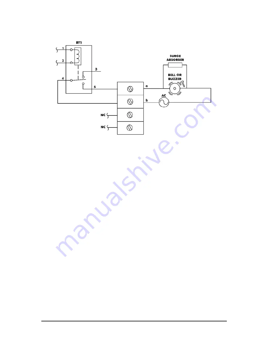
The wiring schematic for the external signal relay circuit is as follows:
Note:
This procedure must be performed with power to both the
external device and the CP-3000 disconnected.
To connect a device to the relay signal circuit, perform the following
steps:
Step 1
. Make sure that power to both the external device and the
CP-3000 is disconnected.
Step 2
. Following the manufacturer’s guidelines for the external device,
connect the signal wires to it and run them to the mounting
location of the CP-3000. Make sure the wires are properly
labeled.
Step 3
. Strip approximately 0.25” (6.35 mm) of insulation off the ends of
the wires that will be connected to the CP-3000.
Step 4
. Remove the top cover from the CP-3000.
Step 5
. Remove the front cover.
Step 6
. With the unit flat and face up, locate terminal block
CN7A/CN7B
, and its corresponding knockout on the bottom of
the housing.
Step 7
. Using a punch or similar object, remove the knockout for
connector
CN7A/CN7B
.
Step 8
. Using a screwdriver, loosen the screws on the
CN7A
side of the
connector block.
Summary of Contents for CP-3000
Page 1: ...CP 3000 Electronic Time Recorder User s Guide ...
Page 6: ...iv CP 3000 User s Guide This page intentionally left blank ...
Page 22: ...2 12 CP 3000 User s Guide This page intentionally left blank ...
Page 30: ...3 8 CP 3000 User s Guide This page intentionally left blank ...
Page 56: ...5 4 CP 3000 User s Guide This page intentionally left blank ...
Page 74: ...7 2 CP 3000 User s Guide ...
Page 75: ......


