Amada MEA-100B Operation Manual Download Page 75

MEA-100B


14. External Communication Function 

14-7 


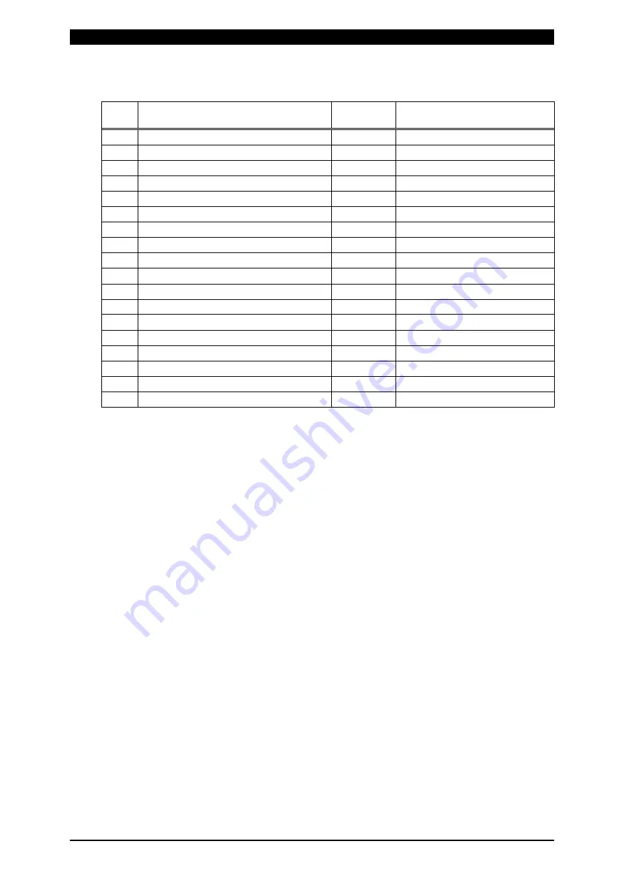
  Screen 03 (Stepper data) Common data (Schedule No.: 00) 

Item 

Contents 

Character 

string 

Range 

SOL1 STEP1 Count 

nnnn, 

0000 to 9999 

SOL1 STEP2 Count 

nnnn, 

0000 to 9999 

SOL1 STEP2 Stepper Rate 

nnn, 

050 to 150 (%) 

SOL1 STEP3 Count 

nnnn, 

0000 to 9999 

SOL1 STEP3 Stepper Rate 

nnn, 

050 to 150 (%) 

SOL1 STEP4 Count 

nnnn, 

0000 to 9999 

SOL1 STEP4 Stepper Rate 

nnn, 

050 to 150 (%) 

SOL1 STEP5 Count 

nnnn, 

0000 to 9999 

SOL1 STEP5 Stepper Rate 

nnn, 

050 to 150 (%) 

10 

SOL2 STEP1 Count 

nnnn, 

0000 to 9999 

11 

SOL2 STEP2 Count 

nnnn, 

0000 to 9999 

12 

SOL2 STEP2 Stepper Rate 

nnn, 

050 to 150 (%) 

13 

SOL2 STEP3 Count 

nnnn, 

0000 to 9999 

14 

SOL2 STEP3 Stepper Rate 

nnn, 

050 to 150 (%) 

15 

SOL2 STEP4 Count 

nnnn, 

0000 to 9999 

16 

SOL2 STEP4 Stepper Rate 

nnn, 

050 to 150 (%) 

17 

SOL2 STEP5 Count 

nnnn, 

0000 to 9999 

18 

SOL2 STEP5 Stepper Rate 

nnn 

050 to 150 (%) 


Summary of Contents for MEA-100B

Page 1: ...Z06OM1200070 10 OPERATION MANUAL Original instructions AC WELDING POWER SUPPLY MEA 100B ...

Page 2: ...ons 1 1 to 1 5 2 Features 2 1 3 Packaging 3 1 4 Name and Functions of Each Section 4 1 to 4 4 5 Connection 5 1 6 Before the Operation 6 1 to 6 4 7 Basic Operation 7 1 to 7 13 8 Stepper Up Function 8 1 to 8 4 9 Detail Settings SET2 Screen 9 1 to 9 7 10 Interface 10 1 to 10 8 11 Timing Chart 11 1 to 11 6 12 Troubleshooting 12 1 to 12 4 13 Specifications 13 1 to 13 8 14 External Communication Functio...

Page 3: ...at may imminently result in serious injury or loss of life if not correctly followed Denotes operations and practices that may result in serious injury or loss of life if not correctly followed Denotes operations and practices that may result in personal injury or damage to the Power Supply if not correctly followed Do not touch the inside of the Power Supply unnecessarily Since very high voltages...

Page 4: ...an cause electric shock and fire If any part needs to be repaired or replaced consult us or your distributor Stop the operation if any trouble occurs Continuous operation after occurrence of a trouble such as burning smell abnormal sound abnormal heat smoke etc can cause electric shock and fire If such a trouble occurs immediately consult us or your distributor Persons with pacemakers must stay cl...

Page 5: ...ire Keep combustible matter away from the welding machine Surface flash and expulsion can ignite combustible matter If it is impossible to remove all combustible matter cover them with non combustible material Do not cover the Power Supply with a blanket cloth etc If such a cover is used it may be overheated and burn Do not use this Power Supply for purposes other than welding Use of this Power Su...

Page 6: ...ate the Welding Power Supply according to the method described in this operation manual Operate the switches and buttons carefully by hand If they are operated roughly or with the tip of a screwdriver a pen etc this will cause malfunction or damage Operate the switches and buttons one at a time If two or more of them are operated at a time the Power Supply may have trouble or may be broken The Pow...

Page 7: ...On Disposal This product incorporates parts containing gallium arsenide GaAs At the time of disposal separate it from general industrial waste or domestic waste and carry out the disposal in accordance with applicable laws and regulations ...

Page 8: ...e Fluctuation Compensation Control Monitors and compensates for power supply voltage fluctuation to maintain a constant current Compensation begins from the first half cycle Single Cycle Welding Power Supply Voltage Fluctuation Compensation Control Permits the flow of one cycle current only You can set the first half wave and the second half wave separately Compensation begins with the first half ...

Page 9: ...to the MEA 100B and connect the MEA 100B to the welding transformer Note If you provide a cable select a cable with the following specification Rated voltage 600 V min Number of cores 3 Cross section 5 5 mm2 min Protection conductor 5 5 mm2 min Cable diameter 18 mm max 1001699 PK 03294 002 5 m 1001712 PK 03294 003 10 m 1001713 For China PK 03887 001 2 m 1001745 PK 03887 002 5 m 1001746 PK 03887 00...

Page 10: ...upply a welding current This lamp is synchronized with Terminal 12 READY of the I O Terminal Strip on the rear panel This lamp lights when the following conditions are met The WELD lamp on the panel is on The WELD ON OFF signal of the I O Terminal Strip on the rear panel is on No trouble has occurred WELD MENU RESET READY START GOOD CAUTION N G SET 1 SET 2 SCHEDULE NO CURR 1 CURR 2 PULSATION SOLEN...

Page 11: ...of the I O Terminal Strip on the rear panel N G Lamp Lights if the items set to 1 on 4 7 of the SET2 screen are troubled See 9 2 Detailed information on the problem is provided on the display panel The lamp is synchronized with Terminals 15 and 16 NG of the I O Terminal Strip on the rear panel WELD Lamp This lamp is one of the three conditions to light the READY lamp Lights when the WELD key is pr...

Page 12: ...rip Terminal strip for signals including the START and NG signals For details see 10 Interface Toroidal Coil Connector This serves as the input connector for the secondary current detection signal Connect the toroidal coil sold separately to this connector when the secondary constant current control is selected or if the power supply voltage fluctuation compensation control is selected and the wel...

Page 13: ...the circuit breaker on and to supply welding power to the MEA 100B Lower the handle to turn off the circuit breaker and to shut off welding power to the MEA 100B Output Terminal Block The output cable sold separately is connected to this block The other end of the cable is connected to the input terminal of the welding transformer For the output cable see 3 2 Options Power Cable Inlet Pass the pow...

Page 14: ... Connect to No 27 and 28 on the I O signal term inal strip M T 5 1 0 A C U V P O W E R O U T 2 19 21 25 26 Toroidal Coil COM 50Hz 60Hz AC200V IN Connect the green wire to Rem ove the terminal cover Connect the green wire to Secondary Cable Connect the green cable to the PE Grounding Green Single phase welding power supply 27 28 Check that the wires and cables are connected to the correct locations...

Page 15: ...een is divided into two general screens the SET1 screen and the SET2 screen To display the SET1 screen press the MENU key and the key simultaneously for at least a second To display the SET2 screen press the MENU key and the key simultaneously for at least a second Also the SET1 screen has 1 and 2 screens and the SET2 screen has 1 to 8 screens The number is displayed at the upper left side on the ...

Page 16: ...n control Multi cycle welding 2 Power supply voltage fluctuation compensation control Single cycle welding 3 Power supply voltage fluctuation compensation control Half cycle welding After changing press the MENU key to go to the welding schedule setting screen 3 Maximum Current Setting The maximum current is set in one of two ways described below A To set the maximum current of the welding machine...

Page 17: ...00 99 cycles b Weld time The set weld time must be the actual weld time 01 99 cycles c The set current must be 60 to 90 of the actual welding current in order to prevent the damage to the MEA 100B caused by overcurrent 0 20 9 99 kA d Weld Force number Select the welding machine for which you want to set the maximum current automatically SOL1 SOL2 Close Terminal 28 START 1ST of the I O Terminal Str...

Page 18: ...key simultaneously for at least a second 1 MAX CURRENT 2 0kA Move the cursor to and change to the 2 screen The 2 LCD CONTRAST screen is displayed 2 LCD CONTRAST 06 Change the value indicated by arrow to select one of 16 contrast levels The lower the value is the darker the LCD is at the bottom line indicates the current contrast level ...

Page 19: ...the MENU screen is displayed An error prompt is displayed if a trouble arises The screen last displayed before power was turned off is displayed on the display panel Attention Do not turn on the circuit breaker while pressing a key on the panel Do not press a key within 2 seconds after power is turned on For example pressing the RESET key during this period will return all welding schedule data to...

Page 20: ... may not be stored normally Be careful when changing settings frequently with the RS 485 bi directional communication The MEA 100B does not have the key to establish setting like ENTER By either of the following procedures settings can be written and stored in the flash memory After changing the set value with the key or key move to the next setting item with the cursor key Settings cannot be stor...

Page 21: ...een Set the schedule for the welding machine being used The MEA 100B can save 31 schedules This screen displays different data according to the welding and control methods selected Current Monitor Range Setting Press the MENU key to go to the Current Monitor Range Setting screen Set the current range of the good welding as the monitor upper limit and lower limit When the current is out of the rang...

Page 22: ...s used the current must not exceed the maximum current setting If it exceeds the maximum current the fault code E14 CURR SETTING ERR is given at start signal input For details see 12 Troubleshooting Current Monitor Range Setting On the basis of the current set for the welding schedule set the allowable ranges in percent Set the ranges for W1 and W2 for each schedule Item Setting Range Display a Sc...

Page 23: ... Current 2 CURR 2 10 0 99 9 Current Monitor Range Setting Set the upper and lower limits in current value Set the limits for W1 and W2 for each schedule Item Setting Range Display a Schedule Number SCHEDULE NO 01 31 schedules b Weld 1 upper limit W1 H 0 00 0 01 9 99 kA c Weld 1 lower limit W1 L 0 00 0 01 9 99 kA d Weld 2 upper limit W2 H 0 00 0 01 9 99 kA e Weld 2 lower limit W2 L 0 00 0 01 9 99 k...

Page 24: ...0 0 99 9 f Weld Force Number SOLENOID 1 2 Current Monitor Range Setting Set the upper and lower limits in current value Set the limits for 1ST and 2ND for each schedule Item Setting Range Display a Schedule Number SCHEDULE NO 01 31 schedules b 1ST upper limit 1ST H 0 00 0 01 9 99 kA c 1ST lower limit 1ST L 0 00 0 01 9 99 kA d 2ND upper limit 2ND H 0 00 0 01 9 99 kA e 2ND lower limit 2ND L 0 00 0 0...

Page 25: ...s d Schedule Number SCHEDULE NO 01 31 schedules e Weld Force Number SOLENOID 1 2 Current Monitor Range Setting Set the upper and lower limits in current value Set the limits for each schedule Item Setting Range Display a Schedule Number SCHEDULE NO 01 31 schedules b HALF upper limit HALF H 0 00 0 01 9 99 kA c HALF lower limit HALF L 0 00 0 01 9 99 kA When set to 0 00 the current is not monitored W...

Page 26: ...ts see 12 Troubleshooting Press the WELD key on the panel The WELD lamp green lights and the MEA 100B is brought into ready state for WELD ON Close Terminals 25 and 26 WELD ON OFF on the rear panel I O terminal strip For details see 10 2 Press and hold down the WELD key for at least a second or open Terminals 25 and 26 on the rear panel I O terminal strip to cancel the welding READY state The WELD...

Page 27: ...B operates with schedule 1 With parity To use the parity function set SS on the SET2 1 screen to 1 See 9 2 Parity check is odd parity When starting combine schedule signals SCH 1 SCH 2 SCH 4 SCH 8 SCH 16 and Parity so that the number of them becomes odd When the total number of the signals is even the fault code E02 START PARITY is given Schedule No SCH 1 SCH 2 SCH 4 SCH 8 SCH 16 Parity 1 1 2 3 4 ...

Page 28: ... 1 2 4 8 16 31 Schedule Input from Panel Operation Display the Welding Schedule Setting screen the Current Monitor Display screen or the Current Monitor Range Setting screen and then input the schedule number you use directly 6 Welding Start When the start signal is input to the I O terminal strip the START lamp lights and the welding sequence starts During the welding sequence the operation curre...

Page 29: ...tem Setting Range Display a Schedule Number SCHEDULE NO Indicates the number of the schedule used for the welding b Monitored current CURR 1 Average effective flowing current during W1 in multi cycle welding 1ST Effective flowing current during the 1ST half cycle in single cycle welding HALF Effective flowing current in half cycle welding c Monitored current CURR 2 Average effective flowing curren...

Page 30: ...ber of the schedule used for welding f W2 weld time Indicates the monitored weld time of W2 g W2 current Indicates the average effective current during W2 h W2 conduction angle Indicates the monitored average conduction angle of W2 Single Cycle Welding Item Setting Range Display a Weld force number Indicates the weld force number used for welding b 1ST current Indicates the effective current in th...

Page 31: ...nal See 12 Troubleshooting for details of faults and 9 2 for the output signal when the fault occurs E07 FULL WAVE or E08 STEP END The count is increased when the output is set to either Trouble signal NG or Caution signal CAUTION E05 LOW CURRENT or E06 HIGH CURRENT The count is increased when the output is set to Caution signal CAUTION Total Count Display Screen The part indicated by an arrow is ...

Page 32: ...current must be reduced to accommodate increased temperatures within an electrode or workpieces Stepper down 1 Turning on the Stepper Up Function Press the MENU key and the key simultaneously for at least a second This displays the SET2 screen shown below Move the cursor to a above Press the key to go to the 2 screen Move the cursor to b above Press the key to change the setting to 1 1 The stepper...

Page 33: ...o move to the Stepper Count Setting Screen Press the key to move the cursor to a above and select the welding head from SOL1 and SOL2 Move the cursor to b and select the stepper number There are 5 stepper numbers 1 stepper 1 to 5 stepper 5 Move the cursor to c and set the stepper counts the weld counts for each stepper number There are 5 stepper numbers 1 stepper 1 to 5 stepper 5 S2 S3 S4 S5 Stepp...

Page 34: ... the cursor to e and select the welding head from SOL1 and SOL2 Move the cursor to a d and set the stepper up rates for steppers 2 5 Set the rate in a percentage to the set value of the welding current expressed as 100 See 7 2 Setting range is 50 to 150 a Up rate for Stepper 2 b Up rate for Stepper 3 c Up rate for Stepper 4 d Up rate for Stepper 5 Setting Example Welding current 0 40 kA Stepper No...

Page 35: ...per counter returns the stepper number to 1 and the stepper counter to 0000 regardless of the current weld count Both the weld force number 1 SOL1 and 2 SOL2 are reset On the stepper up status display screen press the RESET key to go to the reset screen On the reset screen press the RESET key to reset the stepper number and the weld count To cancel the reset press any key other than the RESET key ...

Page 36: ...ings on the SET2 Screen Screen No Settings 1 Key lock Control method Schedule number selection Start signal input Start stabilizing time 2 Stepper up Re weld Weld skip End signal output time Current monitor neglecting cycle 3 No current detecting level No current neglecting cycle 4 7 Fault signal attribute setting screen 8 Communication system Communication speed Device number 1 Screen Display Fun...

Page 37: ... SDT Sets the start stabilizing time at start signal 01 Sets the stabilizing time to 1 ms 05 Sets the stabilizing time to 5 ms 10 Sets the stabilizing time to 10 ms 20 Sets the stabilizing time to 20 ms 05 2 Screen WS and CMI are not indicated if single cycle or half cycle welding is selected Display Function Setting Initial Setting a SU Sets the Stepper up function 0 Stepper up function OFF 1 Ste...

Page 38: ...full cycle The setting can be changed every half cycle 10 0 Ignores errors in the first 10 0 cycles DEF Skips to the next sequence at the time of the WELD SKIP signal is turned from on to off in the sequence If the WELD SKIP signal is turned off it does not skip to the next sequence 3 Screen This screen indicates different data according to the welding and control methods selected Screen for Multi...

Page 39: ...cle 00 0 Detects the no current in all cycles 00 5 Ignores the no current in the first half cycle 01 0 Ignores the no current in the first full cycle The setting is changeable every half cycle 10 0 Ignores the no current in the first 10 0 cycles 01 0 1 The settings of NCL W1 and W2 are different depending on the selected control the secondary constant current control and the power supply voltage f...

Page 40: ...ition Initial Setting a E01 CONTROLLER FAULT Controls trouble 1 Trouble not changeable 1 b E02 START PARITY Result of start parity check is even 0 1 Caution Trouble 1 c E03 SCR OVERHEATING Thyristor overheating 1 Trouble not changeable 1 d E04 NO CURRENT Welding current is not detected No current 0 1 Caution Trouble 1 e E05 LOW CURRENT Welding current is below monitor lower limit 0 1 Caution Troub...

Page 41: ... 1 Caution Trouble 0 k E11 CYCLE TROUBLE Start signal is turned off in welding and then sequence is interrupted Weld cycle trouble 0 1 Caution Trouble 0 l E12 SCR SHORT Thyristor damaged 1 Trouble not changeable 1 m E13 MEMORY TROUBLE Error is detected during self diagnostics 1 Trouble not changeable 1 n E14 CURRENT SETTING ERR Set current exceeds the maximum current 1 Trouble not changeable 1 o E...

Page 42: ...memory of the MEA 100B is 30 000 times To rewrite schedules frequently in the bi directional communication set CONTROL to 2 If the rewriting limit is exceeded data may not be stored normally For storage in the SRAM there is no rewriting limit but if two weeks or more passes after the MEA 100B is powered off data in the memory may be lost Therefore the schedule data at the time of restarting up aft...

Page 43: ...1 SOL2 CAUTION STP WELD END and READY are photo MOS relay outputs When external I O are contacts 入出力端子台 1 2 3 4 5 6 7 8 9 10 11 12 13 14 16 15 17 18 19 20 21 22 23 24 25 26 27 28 29 30 32 33 34 35 31 24V SOL COM SOL1 SOL2 RS485 RS485 CAUTION READY END NG GOOD COM WELD SKIP CNTR RESET ERR RESET STEP RESET COM WELD ON OFF COM START 1ST 2ND STAGE OPTION WELD STOP SCH 16 SCH 8 SCH 4 SCH 1 STP WELD END...

Page 44: ...8 9 10 11 12 13 14 16 15 17 18 19 20 21 22 23 24 25 26 27 28 29 30 32 33 34 35 31 24V SOL COM SOL1 SOL2 RS485 RS485 CAUTION READY END NG GOOD COM WELD SKIP CNTR RESET ERR RESET STEP RESET COM WELD ON OFF COM START 1ST 2ND STAGE OPTION WELD STOP SCH 16 SCH 8 SCH 4 SCH 1 STP WELD END COM 24V 2 EXT 24V EXT GND SCH 2 I O terminal strip ...

Page 45: ...this terminal to the shielded wire of the RS 485 signal cable 7 RS485 8 RS485 Terminals for RS485 and RS485 Connect this terminal to the RS 485 signal cable 9 COM Common terminals when using the Photo MOS relay output with the external power supply 10 CAUTION Output terminal for CAUTION signal When a caution fault occurs this circuit is closed Preset the fault signal attribute so that the caution ...

Page 46: ...stage within the welding sequence are skipped The specific operation depends on the weld skip WS setting as shown below WS 0 Skips to the next stage of the sequence If WELD1 is underway skips to COOL If WELD2 is underway skips to HOLD WS 1 Skips to HOLD 21 WELD STOP Input terminal for STOP signal If this circuit is opened the welding sequence including the welding operation is immediately halted E...

Page 47: ...H signal see 7 4 SS 0 1 Sum of the SCH numbers corresponding to the closed terminals is taken as the selected schedule number SS 2 The SCH number corresponding to the closed terminals is taken as the selected schedule number SS 3 The schedule numbers are set using keys on the panel These terminals are disabled Note For timing details see 11 Timing Chart Note Schedule 1 is selected if no external s...

Page 48: ...onnection to NPN Open Collector Output Device when using the internal power supply To use the internal 24 V power supply connect terminals 1 and 2 with a jumper wire 5V Outside Inside Internal power supply 24V 1 24V 2 EXT 2 24V Short 27 COM 28 START 1ST 5V Outside Inside 24V 1 24V 2 EXT 2 24V Short 27 COM 28 START 1ST Internal power supply ...

Page 49: ...rminal 1 to the terminal of the external 24 V DC power supply Connection to PNP Current Output Type Device Connect terminal 1 to the terminal of the external 24 V DC power supply 5V Outside Inside 1 24V 2 EXT 27 COM 28 START 1ST 24V External power supply 5V Outside Inside 1 24V 2 EXT 28 START 1ST 24V External power supply ...

Page 50: ... Model No Spec Reference Table Connection of SOL1 and SOL2 Relay Output Connection of CAUTION STP WELD END and READY with the external power supply 3 SOL COM 5 SOL2 4 SOL1 24VDC or 250VAC or less 0 5A Outside Inside External power supply Outside Inside 9 COM 10 CAUTION 24VDC 0 1A 24V 11 STP WELD END 12 READY The input power supply has no polarity ...

Page 51: ...s Hold End signal is output until the start signal circuit is opened If the start signal is less than 10 ms or not input then Hold End signal is output for 10 ms 01 Output for 10 ms whether or not the start signal circuit is open 20 Output for 200 ms whether or not the start signal circuit is open Note The Weld End signal is output when the stepper up function SU is not used For the setting of SU ...

Page 52: ...e SDT has elapsed For information on making settings see 9 2 In the case of A above since schedule 1 4 and 16 are ON welding is performed using set data of schedule 21 In the case of B since only schedule 16 is ON welding is performed using set data of schedule 16 Schedule 1 and schedule 4 are not included since they are OFF when the schedule is established Start signal input START 1ST OFF OFF OFF...

Page 53: ...nd during HLD even if input of the start signal is stopped T1 Time required to start weld force after input of the start signal SM on the SET2 screen is set to 1 For the setting of SM see 9 2 The welding sequence runs to completion even if input of the start signal is stopped after starting W1 T1 Time required to start weld force after input of the start signal Welding current SQ UP1 C O UP 2 W 2 ...

Page 54: ... stage start mode The Weld Force signal is output when the 1st stage signal is input Welding begins when the 2nd stage signal is input The welding sequence runs to completion even if input of the start signal is stopped after starting W1 T1 Time required to start weld force after input of the 1st stage signal UP2 DWN SQ UP1 CO W2 W1 HLD T1 OFF OFF Welding current Weld force signal output SOL1 SOL2...

Page 55: ... WELD1 is performed this is output after completion of WELD1 End Signal Output Time HET is set to 00 Output for 10 ms or until start signal is turned off depending on whether the start signal circuit is opened or closed It continues to be output as long as the start signal circuit is closed End Signal Output Time HET is set to 01 Output for 10 ms whether or not the start signal circuit is open CO ...

Page 56: ...urrent During the re weld only the lower limit judgment is performed CO W2 HLD OFF OFF OFF OFF OFF CO W2 OFF OFF OFF OFF OFF 200ms 200ms HLD End signal output END Normal signal output GOOD Welding current Start signal input START 1ST Weld force signal output SOL1 SOL2 Weld end signal output STP WELD END OFF OFF OFF SQ CO W2 W1 HLD CO W2 W1 10cyc Fixed OFF OFF Re weld On detection of trouble On det...

Page 57: ...n Any time during operation Cause of fault The letter in at the end of the message indicates the cause of fault C is displayed when the MEA 100B fails to monitor the frequency of the welding power supply A letter other than C is displayed when the CPU malfunctions Measures Input the error reset signal If the fault occurs repeatedly the welding power supply may be unstable or the MEA 100B has some ...

Page 58: ...he secondary side of the transformer Check if an insulating material is caught between the welding electrodes Adjust the no current detecting level SET2 3 NCL See 9 2 Output signal Outputs the trouble NG signal or the caution CAUTION signal when the fault occurs E05 Message LOW CURRENT Time of detection During welding Cause of fault The current is below the monitor lower limit Measures Check the w...

Page 59: ...h the hold end END signal the step end STP WELD END signal and the normal end GOOD signal when the welding sequence is complete E09 Message STEPUP RATE TROUBLE Time of detection When the start signal is accepted Cause of fault The stepper up current rate exceeds the setting range during the stepper up operation Measures Edit the current up rate so that it falls within the setting range During the ...

Page 60: ...er is turned on Cause of fault An error is found in the schedule or other settings Measures Turn on ERR RESET and then check the schedule and other settings Correct settings Output signal Outputs the trouble NG signal when the error arises E14 Message CURRENT SETTING ERR Time of detection When the start signal is input Cause of fault The current exceeding the maximum current is tried to be set dur...

Page 61: ...ing Single cycle welding Half cycle welding Firing Angle Control Range 20 150 Control Speed Half cycle Welding Current Accuracy Secondary constant current control when the current is set to the maximum value Supply voltage fluctuation Resistance load fluctuation Inductive load fluctuation Power factor angle fluctuation Power supply voltage fluctuation compensation control when the current is set t...

Page 62: ...e HALF 0 5 cycles c Second half wave HALF 0 5 cycles d Hold HLD 00 99 cycles Half cycle welding a Squeeze SQ 00 99 cycles b Half cycle HALF 0 5 cycles c Hold HLD 00 99 cycles Pulsation PL 1 9 times multi cycle welding Maximum Current Setting Range 1 schedule 0 5 9 9 kA in 0 1 kA increment Set to the maximum secondary current of the welding machine being used An automatic setting function is provid...

Page 63: ...ncrement If set to 0 00 kA current monitoring is turned off Current Monitor Cycle Setting Multi cycle welding Select one of the following Weld1 Weld2 Weld1 and Weld2 No check Selection of the monitor range Welding cycle except the first cycle or upslope and downslope Welding cycle except the beginning of the welding to current monitoring cycle 0 10 cycles in 0 5 cycle increment and downslope Singl...

Page 64: ...e No check Half cycle welding Select one of the following Half cycle No check Stepper up 2 schedules SOL1 and SOL2 Stepper No Stepper 1 5 Stepper up rate 50 150 in 1 increment of the set current for Stepper 1 Stepper up weld count 0 9999 Production Counter 0 99999999 Control Input Signal SCH 1 2 4 8 16 Schedule 1 31 schedules represented by binary numbers START 1ST Start input 1st stage 2ND STAGE ...

Page 65: ...Trouble Detection Items Controller fault Stepper up rate error Start parity error Count memory error SCR overheating Weld cycle trouble No current Thyristor shorted Low welding current Self diagnostics error High welding current Current setting error Full wave Weld interrupt trouble Stepper up end Operating Environment Temperature 0 45 C Humidity 90 or less no condensation Altitude 1000 meters or ...

Page 66: ...ly 200 V Ambient temperature 45 C Duty Cycle Primary Effective Current A 3 2 0 2 8 0 2 4 0 2 0 0 1 6 0 1 2 0 8 0 4 0 1 0 0 5 0 1 0 5 1 C Y C 9 9 C Y C 5CYC 10CYC 20CYC 1 0 0 5 0 1 0 5 3 2 0 2 8 0 2 4 0 2 0 0 1 6 0 1 2 0 8 0 4 0 9 9 C Y C 1 C Y C 5CYC 10CYC 20CYC Primary Effective Current A Duty Cycle ...

Page 67: ...bient temperature 45 C 20 0 18 0 16 0 12 0 10 0 6 0 4 0 2 0 8 0 1 00 5 0 1 0 5 14 0 1 C Y C 9 9 C Y C Primary Effective Current A 5CYC 10CYC 20CYC Duty Cycle 2 0 0 1 8 0 1 6 0 1 2 0 1 0 0 6 0 4 0 2 0 8 0 1 0 0 5 0 1 0 5 1 4 0 5CYC 10CYC 20CYC 1 C Y C 9 9 C Y C Primary Effective Current A Duty Cycle ...

Page 68: ...plicable 00 29 220V Photo MOS relay output Internal power supply Not applicable 00 30 220V Photo MOS relay output External power supply Not applicable 00 40 380V Photo MOS relay output Internal power supply Not applicable 00 46 480V Relay output Internal power supply Not applicable 00 48 400V Photo MOS relay output Internal power supply Not applicable 00 49 400V Photo MOS relay output Internal pow...

Page 69: ...status data Prepare the program and its development environment for controlling the Power Supply on the customer side 2 Data Transmission Item Content Transmission mode RS 485 Asynchronous Half duplex Transmission rate Select either of the followings at the SET2 8 screen 9600 19200 38400 bps Data format Start bit 1 Data bit 8 Stop bit 1 Parity bit Even Character code ASCII Checksum data None Conne...

Page 70: ...tional communication mode Otherwise data collision and inappropriate system operations may result Note 3 The RS 232C RS 485 conversion adapter is not included in the accessories It is required to prepare the adapter at customer s side When the switching time from RS 232C mode to RS 485 mode is slow data may not be sent correctly Use a conversion adapter whose switching time is 1 ms or less Host co...

Page 71: ...lding 2 Power supply voltage fluctuation compensation control single cycle welding 3 Power supply voltage fluctuation compensation control half cycle welding D WELD1 Time nn 00 to 99 CYC for Single Cycle and Half Cycle Control E WELD1 Current n nn 0 00 to 9 99 kA F WELD1 Conduction Angle nnn 000 to 180 G WELD2 Time nn 00 to 99 CYC for Single Cycle and Half Cycle Control H WELD2 Current n nn 0 00 t...

Page 72: ...01 to 15 E 1 Error code 3 nn 01 to 15 F 1 Error code 4 nn 01 to 15 G 1 Error code 5 nn 01 to 15 H 1 Error code 6 nn 01 to 15 I 1 Error code 7 nn 01 to 15 J 1 Error code 8 nn 01 to 15 1 The number of error codes is of eight max In the case of only one error code the error codes D to J are omitted E is affixed only to Error code 1 2 Error codes are transmitted when errors are detected For E05 to E08...

Page 73: ...en 04 SYSTEM data Common data Schedule No 00 Screen 05 Monitor data Specific data in accordance with Schedule No Schedule No 01 to 31 Screen 06 Error data Common data Schedule No 00 Setting of data Code Device No W Schedule No S Screen No Data Host I D 1 I D 2 W S H 1 S H 2 S S C 1 S C 2 Data C R L F I D 1 I D 2 S H 1 S H 2 S S C 1 S C 2 Data C R L F MEA 100B 1 ID1 and ID2 are device numbers 2 SH1...

Page 74: ... CC 2 13 HALF Weld current nn n 10 0 to 99 9 CC 3 14 PULSATION Pulsation n 1 to 9 15 SOLENOID Weld force output n 1 2 Screen 02 Upper lower setting data Specific data in accordance with Schedule No Schedule No 01 to 31 Item Contents Character string Range 1 W1 H Weld 1 Current Upper Limit nn 00 to 49 n nn 0 00 to 9 99 kA 2 W1 L Weld 1 Current Lower Limit nn 00 to 49 n nn 0 00 to 9 99 kA 3 W2 H Wel...

Page 75: ...0 to 150 6 SOL1 STEP4 Count nnnn 0000 to 9999 7 SOL1 STEP4 Stepper Rate nnn 050 to 150 8 SOL1 STEP5 Count nnnn 0000 to 9999 9 SOL1 STEP5 Stepper Rate nnn 050 to 150 10 SOL2 STEP1 Count nnnn 0000 to 9999 11 SOL2 STEP2 Count nnnn 0000 to 9999 12 SOL2 STEP2 Stepper Rate nnn 050 to 150 13 SOL2 STEP3 Count nnnn 0000 to 9999 14 SOL2 STEP3 Stepper Rate nnn 050 to 150 15 SOL2 STEP4 Count nnnn 0000 to 9999...

Page 76: ...from the panel 6 SM Self sustaining of the start signal and the welding sequence n 0 Self sustaining from HLD time 1 Self sustaining from W1 time 2 Self sustaining from SQ time 3 2 stage start mode 7 SDT Start stabilizing time at start signal nn 01 1 ms 05 5 ms 10 10 ms 20 20 ms 8 SU Stepper up function n 0 OFF 1 ON 9 RW ON OFF of re weld n 0 OFF 1 ON 10 WS Determines how the MEA 100B functions wh...

Page 77: ...e 27 CYCLE TROUBLE 6 screen E11 n 0 Caution 1 Trouble Screen 05 Monitor data Specific data in accordance with Schedule No Schedule No 01 to 31 Item Contents Character string Range 1 WELD1 Time nn 00 to 99 CYC 2 WELD1 Current n nn 0 00 to 9 99 kA 3 WELD1 Conduction Angle nnn 000 to 180 4 WELD2 Time nn 00 to 99 CYC 5 WELD2 Current n nn 0 00 to 9 99 kA 6 WELD2 Conduction Angle nnn 000 to 180 7 Valve1...

Page 78: ...de 7 nn 01 to 15 8 Error code 8 nn 01 to 15 The number of error codes is of eight max In the case of only one error code the items 2 to 8 are omitted Error reset Data setting only Item Contents Character string Range 1 Error reset nnn E00 00 no error data is returned If an error cannot be reset an error code Enn is returned ...

Page 79: ... SH2 are schedule numbers 00 On the MEA 100B SH1 and SH2 are those of the last welding 08 3 SC1 and SC2 are screen numbers 06 4 In no trouble data of 00 is returned Error reset Code Device No W Schedule No S Screen No Data Example Resets the trouble of the specified device No 01 Host I D 1 I D 2 W S H 1 S H 2 S S C 1 S C 2 Data C R L F 0 1 0 0 0 6 00 0 1 0 0 0 6 E00 I D 1 I D 2 S H 1 S H 2 S S C 1...

Page 80: ...f data Code Device No W Schedule No S Screen No Data Example Write data for a schedule of Screen No 01 of Schedule No 08 of the specified device No 01 Host I D 1 I D 2 W S H 1 S H 2 S S C 1 S C 2 Data C R L F 0 1 0 8 0 1 0 1 0 8 0 1 I D 1 I D 2 S H 1 S H 2 S S C 1 S C 2 Data C R L F MEA 100B Insert between data for a schedule 1 ID1 and ID2 are device numbers 01 2 SH1 and SH2 are schedule numbers 0...

Page 81: ...ase the sequence is executed with the previous welding schedule 3 When changing schedules in the bi directional communication wait until the READY signal is turned on after transmitting data from the host computer side and then move to the next sequence 4 Items 1 to 3 above are applied when CONTROL is set to 2 When writing data in the flash memory when setting CONTROL to 3 the writing time is adde...

Page 82: ...MEA 100B 15 Outline Drawing 15 1 15 Outline Drawing Dimensions in mm 269 118 142 90 69 191 300 418 Front Side Rear Cable Dia 18mm max Cable Dia 14mm max ...

Page 83: ...0 0 99 9 10 0 99 9 00 01 49 or 0 00 0 20 9 99 kA 00 01 49 or 0 00 0 20 9 99 kA 00 01 49 or 0 00 0 20 9 99 kA 00 01 49 or 0 00 0 20 9 99 kA 0 00 0 20 9 99 kA 0 00 0 20 9 99 kA 0 00 0 20 9 99 kA 0 00 0 20 9 99 kA 0 00 0 20 9 99 kA 0 00 0 20 9 99 kA SQ UP1 W1 CO UP2 W2 DWN HLD PULSATION SOLENOID CURR 1 CURR 2 1ST 2ND HALF W1 H W1 L W2 H W2 L 1ST H 1ST L 2ND H 2ND L HALF H HALF L Welding Condi tions C...

Page 84: ...28 27 26 25 24 23 22 21 20 19 18 17 16 SCH Item SQ UP1 W1 CO UP2 W2 DWN HLD PULSATION SOLENOID CURR 1 CURR 2 1ST 2ND HALF W1 H W1 L W2 H W2 L 1ST H 1ST L 2ND H 2ND L HALF H HALF L Welding Condi tions Current Monitor Upper Lower Limit Judg ment ...

Page 85: ...MEA 100B 16 Schedule Table 16 3 Count 0000 9999 Stepper Up Down Rate 050 150 Stepper Up SOL1 STEP1 STEP2 STEP3 STEP4 STEP5 SOL2 STEP1 STEP2 STEP3 STEP4 STEP5 ...

Page 86: ...01 05 10 20 SET2 2 SU 0 1 RW 0 1 WS 0 1 HET 0 1 CMI DEF 0 10 0CYC SET2 3 NCL CC 0 W1 00 10 W2 00 10 CC 1 W1 00 10 W2 00 10 CC 2 1ST 00 10 2ND 00 10 CC 3 HALF 00 10 NCI 00 0 10 0CYC SET2 4 E01 1 1 E02 0 1 E03 1 1 E04 0 1 SET2 5 E05 0 1 E06 0 1 E07 0 2 E08 0 1 SET2 6 E09 1 1 E10 0 1 E11 0 1 E12 1 1 SET2 7 E13 1 1 E14 1 1 E15 1 1 SET2 8 CONTROL 0 3 SPEED 0 2 ID 01 31 ...

Page 87: ......

Reviews: