System Introduction
1-
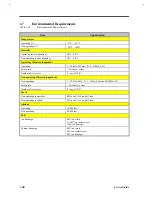
25
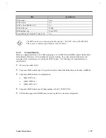
Item
Specification
Performance Specifications
Data transfer rate
(host-buffer, Mbytes/s)
16.6 (max., PIO
mode 4)
16.6 (max., PIO
mode 4)
16.6 (max., PIO
mode 4)
16.6 (max., PIO
mode 4)
DC Power Requirements
Voltage tolerance (V)
5
±
5%
5 + 5%, -10%
5
±
5%
5
±
5%
1.4.20
CD-ROM
Table 1-28
CD-ROM Specifications
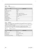
Item
Specification
Vendor & Model Name
Panasonic UJDCD8730
Performance Specification
Speed (KB/sec)
150 (normal speed)
1500 (10X speed)
Access time (ms)
170 (Typ.)
Buffer memory (KB)
128
Interface
Enhanced IDE (ATAPI) compatible
Applicable disc format
CD-DA, CD-ROM, CD-ROM XA (except ADPCM), CD-I,
Photo CD (Multisession), Video CD, CD+
Loading mechanism
Drawer type, manual load/release
Power Requirement
Input Voltage (V)
5
1.4.21
Battery
Table 1-29
Battery Specifications
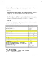
Item
Specification
Battery gauge on screen
Yes, by hotkey
Yes, by hotkey
Yes, by hotkey
Vendor & model name
Sanyo BTP-W31
Sony BTP-T31
Toshiba BTP-X31
Battery type
NiMH
Li-Ion
NiMH
Cell capacity (mAH)
3500
4050
3500
Cell voltage (V)
1.2
3.6
1.2
Number of battery cell
9-cell
9-Cell
9-Cell
Package configuration
9 serial
3 serial, 3 parallel
9 serial
Package voltage (V)
10.8
10.8
10.8
Package capacity (WAH)
37.8
40.5
37.8
Summary of Contents for Extensa 61X
Page 6: ...vi ...
Page 26: ...1 8 Service Guide Figure 1 5 Main Board Layout Bottom Side ...
Page 49: ...System Introduction 1 31 1 5 1 3 Power Management Figure 1 14 Power Management Block Diagram ...
Page 55: ...System Introduction 1 37 1 6 System Block Diagram Figure 1 15 System Block Diagram ...
Page 64: ...Major Chips Description 2 7 2 2 5 Pin Diagram Figure 2 4 M1521 Pin Diagram ...
Page 99: ...2 42 Service Guide 2 5 3 Pin Diagram Figure 2 10 C T 65550 Pin Diagram ...
Page 117: ...2 60 Service Guide Figure 2 12 Functional block diagram CardBus Card Interface ...
Page 119: ...2 62 Service Guide Figure 2 14 PCI to CardBus terminal assignments ...
Page 135: ...2 78 Service Guide 2 7 3 Pin Diagram Figure 2 16 NS87336VJG Pin Diagram ...
Page 145: ...2 88 Service Guide 2 8 2 Pin Diagram Figure 2 17 YMF715 Block Diagram ...
Page 185: ...Disassembly and Unit Replacement 4 5 Figure 4 3 Disassembly Sequence Flowchart ...
Page 209: ...B 2 Service Guide ...
Page 210: ...Exploded View Diagram B 3 ...

