4-22
Service Guide
4.6
Disassembling the Display
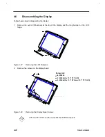
Follow these steps to disassemble the display:
1.
Remove the oval LCD bumpers at the top of the display and the long bumper on the LCD
hinge.
Figure 4-27
Removing the LCD Bumpers
2.
Remove five screws on the display bezel.
or
Screw List:
x4, M2.5L6
x1, M2.5L6(for TFT LCD)
x1, M2.5x8(for STN LCD)
Figure 4-28
Removing the Display Bezel Screws
STN and TFT LCDs use the same bezel but different panels.
Screw List:
x4, M2.5L6
x1, M2.5L6(for 11.3” TFT LCD)
x1, M2.5x8(for 11.3” STN and 12.1” TFT LCD)
Summary of Contents for Extensa 61X
Page 6: ...vi ...
Page 26: ...1 8 Service Guide Figure 1 5 Main Board Layout Bottom Side ...
Page 49: ...System Introduction 1 31 1 5 1 3 Power Management Figure 1 14 Power Management Block Diagram ...
Page 55: ...System Introduction 1 37 1 6 System Block Diagram Figure 1 15 System Block Diagram ...
Page 64: ...Major Chips Description 2 7 2 2 5 Pin Diagram Figure 2 4 M1521 Pin Diagram ...
Page 99: ...2 42 Service Guide 2 5 3 Pin Diagram Figure 2 10 C T 65550 Pin Diagram ...
Page 117: ...2 60 Service Guide Figure 2 12 Functional block diagram CardBus Card Interface ...
Page 119: ...2 62 Service Guide Figure 2 14 PCI to CardBus terminal assignments ...
Page 135: ...2 78 Service Guide 2 7 3 Pin Diagram Figure 2 16 NS87336VJG Pin Diagram ...
Page 145: ...2 88 Service Guide 2 8 2 Pin Diagram Figure 2 17 YMF715 Block Diagram ...
Page 185: ...Disassembly and Unit Replacement 4 5 Figure 4 3 Disassembly Sequence Flowchart ...
Page 209: ...B 2 Service Guide ...
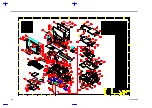
Page 210: ...Exploded View Diagram B 3 ...


