vii
Table of Contents
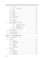
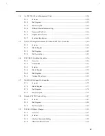
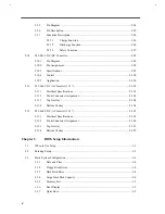
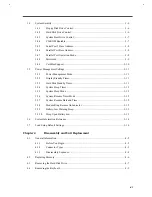
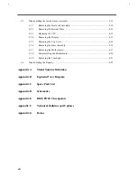
Overview.......................................................................................................................... 1-1
Features ........................................................................................................... 1-2
Rear Ports ........................................................................................................ 1-3
Indicator Light ................................................................................................. 1-4
System Specifications Overview ....................................................................... 1-5
System Board Layout........................................................................................................ 1-7
Main Board (PCB No: 96149-SC) .................................................................... 1-7
Audio Connection Board (PCB No:96467-1) .................................................... 1-9
Battery Connection Board (PCB No:95498-1) .................................................. 1-9
HDD Connection Board (PCB No:96463-1) ................................................... 1-10
Keyboard Connection Board (PCB No: 96465-1)............................................ 1-11
Jumpers and Connectors................................................................................................. 1-12
Hardware Configuration and Specification ..................................................................... 1-14
Memory Address Map .................................................................................... 1-14
Interrupt Channel Map................................................................................... 1-14
DMA Channel Map ....................................................................................... 1-15
I/O Address Map............................................................................................ 1-15
M7101 GPIO (General Purpose I/O) Port Definition ...................................... 1-16
Processor........................................................................................................ 1-16
BIOS.............................................................................................................. 1-17
System Memory ............................................................................................. 1-17
Second-Level Cache....................................................................................... 1-18
Video Memory ............................................................................................... 1-19
Video ............................................................................................................. 1-19
External CRT Resolution Support ............................................... 1-19
LCD Resolution Support ............................................................. 1-20
Parallel Port ................................................................................................... 1-21
Serial Port ...................................................................................................... 1-21
Audio............................................................................................................. 1-22
PCMCIA........................................................................................................ 1-22
Touchpad ....................................................................................................... 1-23
Summary of Contents for Extensa 61X
Page 6: ...vi ...
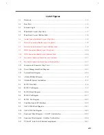
Page 26: ...1 8 Service Guide Figure 1 5 Main Board Layout Bottom Side ...
Page 49: ...System Introduction 1 31 1 5 1 3 Power Management Figure 1 14 Power Management Block Diagram ...
Page 55: ...System Introduction 1 37 1 6 System Block Diagram Figure 1 15 System Block Diagram ...
Page 64: ...Major Chips Description 2 7 2 2 5 Pin Diagram Figure 2 4 M1521 Pin Diagram ...
Page 99: ...2 42 Service Guide 2 5 3 Pin Diagram Figure 2 10 C T 65550 Pin Diagram ...
Page 117: ...2 60 Service Guide Figure 2 12 Functional block diagram CardBus Card Interface ...
Page 119: ...2 62 Service Guide Figure 2 14 PCI to CardBus terminal assignments ...
Page 135: ...2 78 Service Guide 2 7 3 Pin Diagram Figure 2 16 NS87336VJG Pin Diagram ...
Page 145: ...2 88 Service Guide 2 8 2 Pin Diagram Figure 2 17 YMF715 Block Diagram ...
Page 185: ...Disassembly and Unit Replacement 4 5 Figure 4 3 Disassembly Sequence Flowchart ...
Page 209: ...B 2 Service Guide ...
Page 210: ...Exploded View Diagram B 3 ...


