Date:
February 12, 1997
Sheet
9
of
25
Size
Document Number
REV
A3
96149
SC
Title
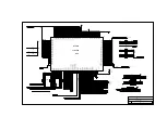
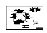
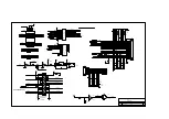
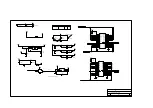
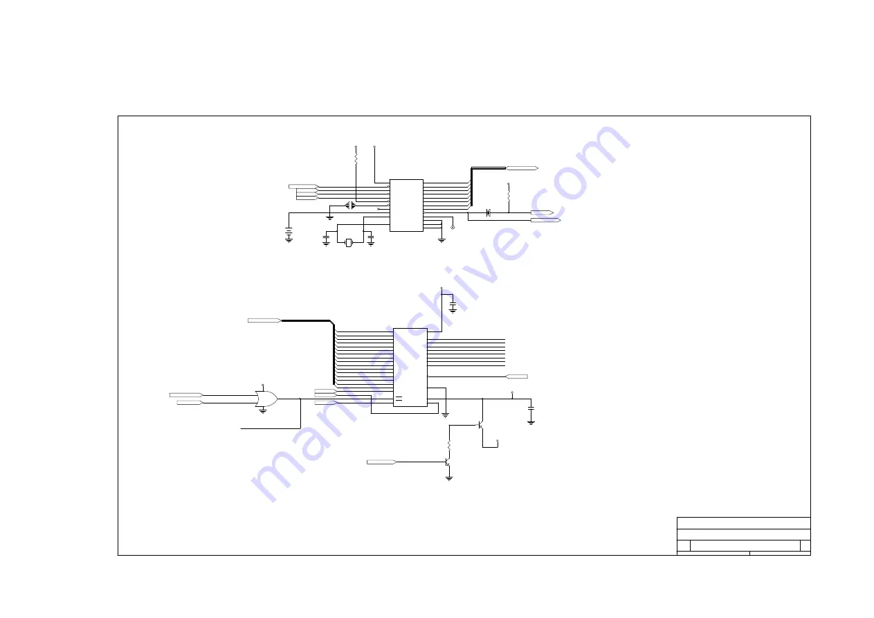
370P/J (RTC AND BIOS)
TAIPEI TAIWAN R.O.C
ACER
1
2
R9
10KR3
SD[0..7]
IRQ8#
IRQ8#
SD[0..7]
+5V
4,8
4,10,11,13,15
1
2
DX2
S1N4148
RTCIRQ8#
VCC
24
CS$
13
AS
14
R/W$
15
DS
17
RST$
18
RCL$
21
EXTRAM
22
BC
20
X1
2
X2
3
AD7
11
AD6
10
AD5
9
AD4
8
AD3
7
AD2
6
AD1
5
AD0
4
INT$
19
SQW
23
MOT
1
VSS
12
VSS
16
U27
BQ3285E
1
2
R35
10KR3
2
1
G1
GAP-OPEN
RTCAS
RTCRW
RTCDS
PWRGOOD#
RTCAS
RTCRW
RTCDS
SD7
SD1
SD2
SD3
SD4
SD5
SD6
SD0
+5V
+5V
4
TPX3
TP-1
U40 PIN 22
SB: ADD DUMMY RESISTER TO
PWRGOOD#
23
24
24
1
2
BT1
BH-12
SA[0..15]
4
C265
SCD1U
1
2
X1
XTAL-32.768KHZ
A0
20
A1
19
A2
18
A3
17
A4
16
A5
15
A6
14
A7
13
A8
3
A9
2
A10
31
A11
1
A12
12
A13
4
A14
5
A15
11
A16
10
CE
30
VCC
8
VSS
24
VPP
9
DQ0
21
DQ1
22
DQ2
23
DQ3
25
DQ4
26
DQ5
27
DQ6
28
DQ7
29
WE#
7
OE
32
A17
6
U52
28F020-1
SA0
HDD+5V
CX30
SC3P50V3KN
CX31
SC3P50V3KN
3
2
1
Q8
S2N3906
C266
SCD1U
MEMW#
SD0
SD1
SD2
SD3
SD4
SD5
SD6
SD7
MEMW#
+12V
BIOSVPP
4
1
2
R222
10KR3
MEMR#
XSA16
XSA17
SA1
SA2
SA3
SA4
SA5
SA6
SA7
SA8
SA9
SA10
SA11
SA12
SA13
SA14
SA15
MEMR#
U52 IS TSOP PACKAGE,
MUST BE INSTALL.
4
8
8
9
10
8
1
4
7
U45C
SSHCT32
RTCROMCS#
DISROM
RTCROMCS#
DISROM
BIOSCE#
+5V
4
13
3
1
2
Q9
RN1424
FLASH_ON
FLASH_ON
8
## REMOVE U53 PAD
Summary of Contents for Extensa 61X
Page 6: ...vi ...
Page 26: ...1 8 Service Guide Figure 1 5 Main Board Layout Bottom Side ...
Page 49: ...System Introduction 1 31 1 5 1 3 Power Management Figure 1 14 Power Management Block Diagram ...
Page 55: ...System Introduction 1 37 1 6 System Block Diagram Figure 1 15 System Block Diagram ...
Page 64: ...Major Chips Description 2 7 2 2 5 Pin Diagram Figure 2 4 M1521 Pin Diagram ...
Page 99: ...2 42 Service Guide 2 5 3 Pin Diagram Figure 2 10 C T 65550 Pin Diagram ...
Page 117: ...2 60 Service Guide Figure 2 12 Functional block diagram CardBus Card Interface ...
Page 119: ...2 62 Service Guide Figure 2 14 PCI to CardBus terminal assignments ...
Page 135: ...2 78 Service Guide 2 7 3 Pin Diagram Figure 2 16 NS87336VJG Pin Diagram ...
Page 145: ...2 88 Service Guide 2 8 2 Pin Diagram Figure 2 17 YMF715 Block Diagram ...
Page 185: ...Disassembly and Unit Replacement 4 5 Figure 4 3 Disassembly Sequence Flowchart ...
Page 209: ...B 2 Service Guide ...
Page 210: ...Exploded View Diagram B 3 ...


