xiii
List of Figures
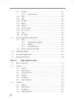
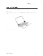
Notebook.......................................................................................................................... 1-1
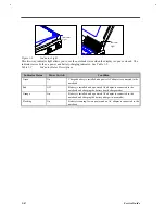
Rear Ports ........................................................................................................................ 1-3
Indicator Light ................................................................................................................. 1-4
Main Board Layout (Top Side) ......................................................................................... 1-7
Main Board Layout (Bottom Side).................................................................................... 1-8
Audio Connection Board Layout (Top Side)
..................................................................... 1-9
Battery Connection Board Layout (Top Side)
................................................................... 1-9
Battery Connection Board Layout (Bottom Side)
.............................................................. 1-9
HDD Connection Board Layout (Top Side)
.................................................................... 1-10
HDD Connection Board Layout (Bottom Side)
............................................................... 1-10
Keyboard Connection Board Layout (Top Side)
.............................................................. 1-11
Keyboard Connection Board Layout (Bottom Side)
......................................................... 1-11
Jumpers and Connectors (Top View).............................................................................. 1-12
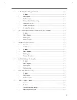
Power Management Block Diagram ............................................................................... 1-31
System Block Diagram ................................................................................................... 1-38
Alladin III Block Diagram ............................................................................................... 2-4
Alladin III System Architecture........................................................................................ 2-5
M1521 Data Path ............................................................................................................. 2-6
M1521 Pin Diagram......................................................................................................... 2-7
M1523 Block Diagram ................................................................................................... 2-16
M1523 Pin Diagram....................................................................................................... 2-17
M7101 Pin Diagram...................................................................................................... 2-25
State Machine for PCI Interface ..................................................................................... 2-39
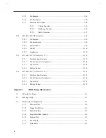
C&T 65550 Block Diagram............................................................................................ 2-41
C&T 65550 Pin Diagram ............................................................................................... 2-42
Functional Block Diagram - 16-bit PC Card Interface .................................................... 2-59
Functional block diagram - CardBus Card Interface ....................................................... 2-60
PCI-to-PC Card (16-bit) terminal assignments ............................................................... 2-61
Summary of Contents for Extensa 61X
Page 6: ...vi ...
Page 26: ...1 8 Service Guide Figure 1 5 Main Board Layout Bottom Side ...
Page 49: ...System Introduction 1 31 1 5 1 3 Power Management Figure 1 14 Power Management Block Diagram ...
Page 55: ...System Introduction 1 37 1 6 System Block Diagram Figure 1 15 System Block Diagram ...
Page 64: ...Major Chips Description 2 7 2 2 5 Pin Diagram Figure 2 4 M1521 Pin Diagram ...
Page 99: ...2 42 Service Guide 2 5 3 Pin Diagram Figure 2 10 C T 65550 Pin Diagram ...
Page 117: ...2 60 Service Guide Figure 2 12 Functional block diagram CardBus Card Interface ...
Page 119: ...2 62 Service Guide Figure 2 14 PCI to CardBus terminal assignments ...
Page 135: ...2 78 Service Guide 2 7 3 Pin Diagram Figure 2 16 NS87336VJG Pin Diagram ...
Page 145: ...2 88 Service Guide 2 8 2 Pin Diagram Figure 2 17 YMF715 Block Diagram ...
Page 185: ...Disassembly and Unit Replacement 4 5 Figure 4 3 Disassembly Sequence Flowchart ...
Page 209: ...B 2 Service Guide ...
Page 210: ...Exploded View Diagram B 3 ...


