Major Chips Description
2-71
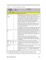
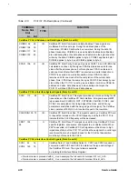
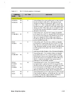
Table 2-13
PCI1131 Pin Descriptions (Continued)
TERMINAL
Name Slot
Slot
I/O
TYPE
FUNCTION
A+ B
≠≠
CardBus PC Card Interface Control Signals (Slots A and B)
CBLOCK 107 42
I/O
CardBus Lock. This is an optional signal used to lock a particular
address, ensuring a bus initiator exclusive access. NOTE: This signal is
not supported on the PCI 1131.
CDEVSEL 111 47
I/O
CardBus Device Select. When actively driven, this signal indicates that
the PCI 1131 has decoded its address as the target of the current
access. As an input, CDEVSEL indicates whether any device
on the bus has been selected.
CDEVSEL 109 45
I/O
CardBus Stop. This signal indicates the current target is requesting the
initiator to stop the current transaction.
CSTSCHG 138 72
I
CardBus Status Change. CSTSCHG is used to alert the system to a
change in the READY, WP, or BVD condition of the l/O CardBus PC
Card.
CAUDIO 137
71
I
CardBus Audio. This signal is an optional digital input signal from a PC
Card to the system's speaker. CardBus cards support two types of audio:
single amplitude, binary waveform, and/or Pulse Width Modulation
(PWM) encoded signal. The PCI1131 supports the Binary Audio Mode,
and may output a binary audio signal from the PC Card to the
SPKROUT signal.
CIRDY 115 50
I/O
CardBus Initiator Ready. This signal indicates that the PCI1131 is
initiating the bus initiator ability to complete a current data phase of the
transaction. It is used in conjunction with CTRDY. When both of these
signals are sampled asserted, a data phase is completed on any clock.
During a write, CIRDY indicates that valid data is present on CAD31-0,
and during a read, it indicates the PCI 1131, as an initiator, is prepared
to accept the data. Wait cycles are inserted until both CTRDY and
CFRDY are both low (asserted).
CTRDY 114 49
I/O
CardBusTargetReady. This signal indicates that the PCI 1131, as a
selected targets has the ability to complete a current data phase of the
transaction. It is used in conjunction with CIRDY. When both of these
signals are sampled asserted, a data phase is completed on any clock.
During a read, CTRDY indicates that valid data is present on CAD31-0,
and during a write, it indicates the PCI 1131, as a target, is prepared to
accept the data. Wait cycles are inserted until both CIRDY and CTRDY
are both low (asserted).
CFRAME 116 51
I/O
CardBus Cycle Frame. This signal is driven by the PCI 1131 when it is
acting as an initiator to indicate the beginning and duration of a
transaction. CFRAME is asserted to indicated a bus transaction is
beginning, and while it is asserted, data transfer is continuous. When
CFRAME is high (deasserted), the transaction is in its final data phase.
+
Terminal name is preceded with A_. As an example, the full name for terminal 121 is A_A25.
≠
Terminal name is preceded with B_. As an example, the full name for terminal 55 is B_A25.
Summary of Contents for Extensa 61X
Page 6: ...vi ...
Page 26: ...1 8 Service Guide Figure 1 5 Main Board Layout Bottom Side ...
Page 49: ...System Introduction 1 31 1 5 1 3 Power Management Figure 1 14 Power Management Block Diagram ...
Page 55: ...System Introduction 1 37 1 6 System Block Diagram Figure 1 15 System Block Diagram ...
Page 64: ...Major Chips Description 2 7 2 2 5 Pin Diagram Figure 2 4 M1521 Pin Diagram ...
Page 99: ...2 42 Service Guide 2 5 3 Pin Diagram Figure 2 10 C T 65550 Pin Diagram ...
Page 117: ...2 60 Service Guide Figure 2 12 Functional block diagram CardBus Card Interface ...
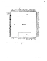
Page 119: ...2 62 Service Guide Figure 2 14 PCI to CardBus terminal assignments ...
Page 135: ...2 78 Service Guide 2 7 3 Pin Diagram Figure 2 16 NS87336VJG Pin Diagram ...
Page 145: ...2 88 Service Guide 2 8 2 Pin Diagram Figure 2 17 YMF715 Block Diagram ...
Page 185: ...Disassembly and Unit Replacement 4 5 Figure 4 3 Disassembly Sequence Flowchart ...
Page 209: ...B 2 Service Guide ...
Page 210: ...Exploded View Diagram B 3 ...


