1-
22
Service Guide
1.4.14
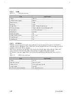
Audio
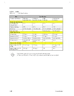
Table 1-21
Audio Specifications
Item
Specification
Chipset
YMF715
Audio onboard or optional
Built-in
Mono or stereo
Stereo
Resolution
16-bit
Compatibility
SB-16 , Windows Sound System
Mixed sound sources
Voice, Synthesizer, Line-in, Microphone, CD
Voice channel
8-/16-bit, mono/stereo
Sampling rate
44.1 kHz
Internal microphone
No
Internal speaker / quantity
Yes / 2 pcs.
Microphone jack
Yes
Headphone jack
Yes
1.4.15
PCMCIA
PCMCIA is an acronym for Personal Computer Memory Card International Association. The PCMCIA
committee set out to standardize a way to add credit-card size peripheral devices to a wide range of personal
computers with as little effort as possible.
There are two type II/I or one type III PC Card slots found on the left panel of the notebook. These slots
accept credit-card-sized cards that enhances the usability and expandability of the notebook.
ZV (Zoomed Video) port support allows your system to support hardware MPEG in the form of a ZV PC
card.
Table 1-22
PCMCIA Specifications
Item
Specification
Chipset
TI 1131
Supported card type
Type-II / Type-III
Number of slots
Two Type-II or one Type-III
Access location
Left side
ZV (Zoomed Video) port support
Yes (only in lower slot)
Summary of Contents for Extensa 61X
Page 6: ...vi ...
Page 26: ...1 8 Service Guide Figure 1 5 Main Board Layout Bottom Side ...
Page 49: ...System Introduction 1 31 1 5 1 3 Power Management Figure 1 14 Power Management Block Diagram ...
Page 55: ...System Introduction 1 37 1 6 System Block Diagram Figure 1 15 System Block Diagram ...
Page 64: ...Major Chips Description 2 7 2 2 5 Pin Diagram Figure 2 4 M1521 Pin Diagram ...
Page 99: ...2 42 Service Guide 2 5 3 Pin Diagram Figure 2 10 C T 65550 Pin Diagram ...
Page 117: ...2 60 Service Guide Figure 2 12 Functional block diagram CardBus Card Interface ...
Page 119: ...2 62 Service Guide Figure 2 14 PCI to CardBus terminal assignments ...
Page 135: ...2 78 Service Guide 2 7 3 Pin Diagram Figure 2 16 NS87336VJG Pin Diagram ...
Page 145: ...2 88 Service Guide 2 8 2 Pin Diagram Figure 2 17 YMF715 Block Diagram ...
Page 185: ...Disassembly and Unit Replacement 4 5 Figure 4 3 Disassembly Sequence Flowchart ...
Page 209: ...B 2 Service Guide ...
Page 210: ...Exploded View Diagram B 3 ...


