2-72
Service Guide
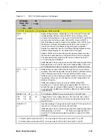
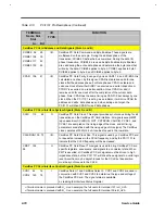
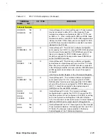
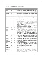
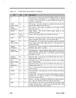
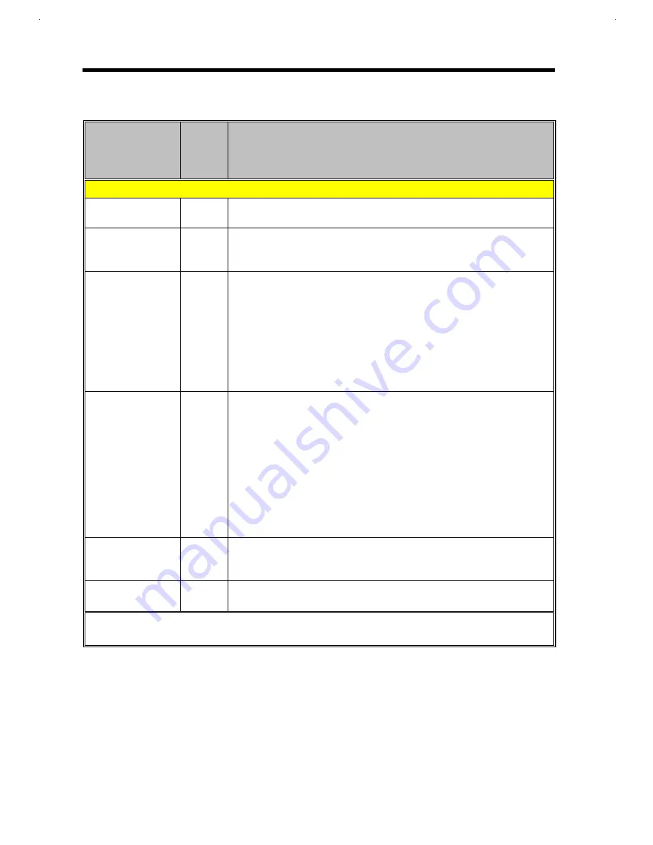
Table 2-13
PCI1131 Pin Descriptions (Continued)
TERMINAL
Name Slot
Slot
I/O
TYPE
FUNCTION
A+ B
≠≠
CardBus PC Card Interface Control Signals (Slots A and B)
CREQ
127 61
I
CardBus Request. This signal ir1dicates to the arbiter that the CardBus
PC Card desires use the CardBus bus.
CGNT
110 46
O
CardBus Grant. This signal is driven by the PCI 1131 to grant a CardBus
PC Card access to the CardBus bus after the current data transaction
has completed
CPERR 108 43
I/O
CardBus Parity Error. This signal reports errors during all CardBus PC
Card transactions except during special cycles. This signal is sustained
in a high-impedance state and must be driven active by the agent
receiving data, two clocks following the data, when a data parity error is
detected. This signal must be driven active for a minimum duration is
one clock for each data phase. CPERR must be driven high for one clock
before it is returned to the high-impedance state. An agent cannot report
a CPERR until it has claimed the access by asserting CDSVSEL and
completed a data phase.
CSERR 136 70
I
CardBus System Error. This signal reports address parity error, data
errors on the Special Cycle command, or any other system error where
the result could be catastrophic, such that the CardBus card may no
longer operate correctly. CSERR is open drain and is actively driven for
a single CardBus PC Card clock by the agent reporting the error. The
assertion of this signal is synchronous to the Cock and meets the setup
and hold times of all bussed signals. Restoring of the CSERR to the
deasserted states is accomplished by a weak pull-up which is provided
by the system designer. This pull-up may take two to three clock periods
to fully restore ~R The PCI1131 reports CSERR to the operating system
anytime it is sampled low (asserted)
CVS1
134 68
CVS2
122 56
I/O
CardBus Voltage Sense 1 and Voltage Sense 2. CVS1 and CVS2, are
used in conjunction with each other, along with CCD1 and CCD2, to
determine the operating voltage of the CardBus PC Card.
CINT
135 69
I
CardBus Interrupt. This signal is asserted low by a CardBus PC Card to
request interrupt servicing from the host.
+
Terminal name is preceded with A_. As an example, the full name for terminal 121 is A_A25.
≠
Terminal name is preceded with B_. As an example, the full name for terminal 55 is B_A25.
Summary of Contents for Extensa 61X
Page 6: ...vi ...
Page 26: ...1 8 Service Guide Figure 1 5 Main Board Layout Bottom Side ...
Page 49: ...System Introduction 1 31 1 5 1 3 Power Management Figure 1 14 Power Management Block Diagram ...
Page 55: ...System Introduction 1 37 1 6 System Block Diagram Figure 1 15 System Block Diagram ...
Page 64: ...Major Chips Description 2 7 2 2 5 Pin Diagram Figure 2 4 M1521 Pin Diagram ...
Page 99: ...2 42 Service Guide 2 5 3 Pin Diagram Figure 2 10 C T 65550 Pin Diagram ...
Page 117: ...2 60 Service Guide Figure 2 12 Functional block diagram CardBus Card Interface ...
Page 119: ...2 62 Service Guide Figure 2 14 PCI to CardBus terminal assignments ...
Page 135: ...2 78 Service Guide 2 7 3 Pin Diagram Figure 2 16 NS87336VJG Pin Diagram ...
Page 145: ...2 88 Service Guide 2 8 2 Pin Diagram Figure 2 17 YMF715 Block Diagram ...
Page 185: ...Disassembly and Unit Replacement 4 5 Figure 4 3 Disassembly Sequence Flowchart ...
Page 209: ...B 2 Service Guide ...
Page 210: ...Exploded View Diagram B 3 ...

