Date:
February 12, 1997
Sheet
24
of
25
Size
Document Number
REV
A3
96149
SC
Title
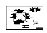
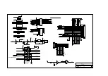
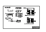
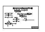
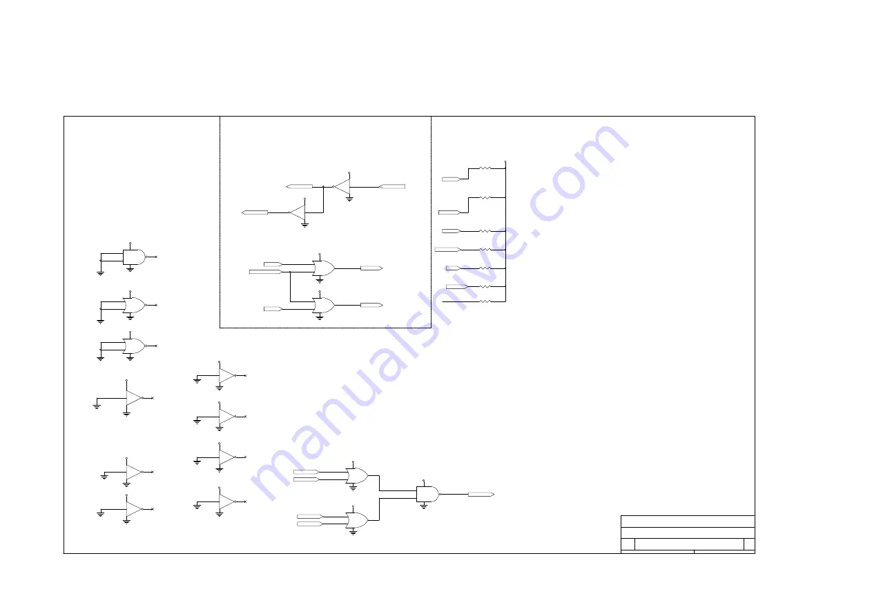
370P/J (H/W JUMPER SETTING)
TAIPEI TAIWAN R.O.C
ACER
ALADDIN III
PULL L: 5V suspend mode enable.
PULL H: 5V suspend mode disable.
L: DMA DACK[7:5,3:0] polling enable.
H: DMA DACK[7:5,3:0] polling disable.
*** If L, add ALDN3 P.21 MUX!
1
2
R171
10KR3
1
2
R43
10KR3
XDIR
SPLED
+5V
4
4
COMMON
3
4
1
4
7
U41B
SSHCT04
1
2
1
4
7
U41A
SSHCT04
$CPURST
PCIRST#
RSTDRV
+5V
+5V
4
3,10,14,17,21,22
11,13,15
+5V
9
10
8
1
4
7
U17C
SSHC00
5VSB_DC
2
3
1
1
4
7
U1XA
SSHC02
POWER: VCC_IDE & GND
1
2
3
1
4
7
U45A
SSHCT32
4
5
6
1
4
7
U45B
SSHCT32
IOW#
RTCROMCS#
IOR#
RTCDS
RTCRW
+5V
+5V
4
4
4
9
9
L: Internal keyboard cntrler enable.
H: Internal KBC disable.
L: Internal RTC enable.
H: Internal RTC disable.
L: External I/O APIC mode supported.
H: Ext. I/O APIC mode not supported.
Must pull High.
*** Refer to CKT down left.
1
2
R42
10KR3
1
2
R20
10KR3
1
2
R38
10KR3
1
2
R173
10KR3
1
2
R170
560R3
SPKR
PHOLD#
TC
KBCS#
RTCROMCS#
4
4
4
9
8
1
4
7
U46D
SSHCT04
5
6
1
4
7
U46C
SSHCT04
+5V
+5V
5VSB_DC
11
12
13
1
4
7
U1XD
SSHC02
9
8
1
4
7
U38D
SSHC14
+5V
11
10
1
4
7
U41E
SSHCT04
13
12
1
4
7
U41F
SSHCT04
+5V
+5V
+5V
11
10
1
4
7
U46E
SSHCT04
1
2
1
4
7
U46A
SSHCT04
+5V
12
13
11
1
4
7
U45D
SSHCT32
1
2
3
1
4
7
U44A
SSHCT32
A_CD1#
A_CD2#
B_CD1#
B_CD2#
+5V
+5V
22
22
22
22
12
13
11
1
4
7
U17D
SSHC00
EXCACD#
+5V
8
Summary of Contents for Extensa 61X
Page 6: ...vi ...
Page 26: ...1 8 Service Guide Figure 1 5 Main Board Layout Bottom Side ...
Page 49: ...System Introduction 1 31 1 5 1 3 Power Management Figure 1 14 Power Management Block Diagram ...
Page 55: ...System Introduction 1 37 1 6 System Block Diagram Figure 1 15 System Block Diagram ...
Page 64: ...Major Chips Description 2 7 2 2 5 Pin Diagram Figure 2 4 M1521 Pin Diagram ...
Page 99: ...2 42 Service Guide 2 5 3 Pin Diagram Figure 2 10 C T 65550 Pin Diagram ...
Page 117: ...2 60 Service Guide Figure 2 12 Functional block diagram CardBus Card Interface ...
Page 119: ...2 62 Service Guide Figure 2 14 PCI to CardBus terminal assignments ...
Page 135: ...2 78 Service Guide 2 7 3 Pin Diagram Figure 2 16 NS87336VJG Pin Diagram ...
Page 145: ...2 88 Service Guide 2 8 2 Pin Diagram Figure 2 17 YMF715 Block Diagram ...
Page 185: ...Disassembly and Unit Replacement 4 5 Figure 4 3 Disassembly Sequence Flowchart ...
Page 209: ...B 2 Service Guide ...
Page 210: ...Exploded View Diagram B 3 ...


