Date:
February 12, 1997
Sheet
20
of
25
Size
Document Number
REV
A3
96149
SC
Title
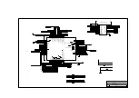
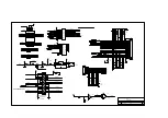
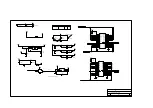
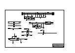
370P/J (LCD I/F)
TAIPEI TAIWAN R.O.C
ACER
CRT_R
CRT_G
CRT_B
19
19
19
1
2
L9
NL322522T-2R2
1
2
L10
NL322522T-2R2
1
2
L11
NL322522T-2R2
C14
SC47P
C13
SC47P
1
2
R13
10R3
1
2
R14
10R3
1
2
R16
10R3
1
2
R19
75R3
1
2
R18
75R3
1
2
R17
75R3
C12
SC47P
RGBGND
1
2
3
D2
BAV99LT1
1
2
3
D1
BAV99LT1
1
2
3
D3
BAV99LT1
R
G
B
+5V
17
17
17
1
2
R111
22R3
1
2
R155
10R3
C204
SC33P
1
2
R165
10R3
C218
SC33P
1
2
R121
22R3
1
2
R117
22R3
C217
SC33P
1
2
R162
10R3
FLM
LP
MOD
PLFS
PLP
PMOD
PLFS
PLP
PMOD
17
17
17
1
2
R157
22R3
1
2
R132
0R3
1
2
3
D5
BAV99LT1
HSYNC
VSYNC
17
17
19
19
19
THESE COMPONENTS 68.00031.001
1
2
R40
10R3
1
2
R39
10R3
1
2
L14
BK2125HS330
1
2
L15
BK2125HS330
C17
SC47P
C16
SC47P
1
2
3
D4
BAV99LT1
+5V
CRT_HS
CRT_VS
19
19
LCD_DISPLAY
19
DISPLAY
DISPLAY
3.3V
2
3
1
4
1
7
U13A
SOLCX125M
8
1
2
R56
22R3
GPIORF1#
LIB/MH#
AD16
CPU_TH
AD17
+5V
2
3,4,8,17,21
3,4,8,17,21
23
8
19
12
11
1
4
1
3
7
U26D
SSHC125
3.3V
9
8
1
4
1
0
7
U34C
SSLVC125
U26 MUST BE 74AHC125
1
2
CN8
CON2-10
1
2
R128
100R3
C2
SC100P
SHFCLK
PSHFCLK
PSHFCLK
+5V
17
C212
SC56P
1
2
R4
10KR3
2
3
1
4
1
7
U26A
SSHC125
ENBL
COVER_SW
COVER_SW
+5V
8
8
1
2
R134
10KR3
1
2
R133
100R3
CCFT_ON
19
Summary of Contents for Extensa 61X
Page 6: ...vi ...
Page 26: ...1 8 Service Guide Figure 1 5 Main Board Layout Bottom Side ...
Page 49: ...System Introduction 1 31 1 5 1 3 Power Management Figure 1 14 Power Management Block Diagram ...
Page 55: ...System Introduction 1 37 1 6 System Block Diagram Figure 1 15 System Block Diagram ...
Page 64: ...Major Chips Description 2 7 2 2 5 Pin Diagram Figure 2 4 M1521 Pin Diagram ...
Page 99: ...2 42 Service Guide 2 5 3 Pin Diagram Figure 2 10 C T 65550 Pin Diagram ...
Page 117: ...2 60 Service Guide Figure 2 12 Functional block diagram CardBus Card Interface ...
Page 119: ...2 62 Service Guide Figure 2 14 PCI to CardBus terminal assignments ...
Page 135: ...2 78 Service Guide 2 7 3 Pin Diagram Figure 2 16 NS87336VJG Pin Diagram ...
Page 145: ...2 88 Service Guide 2 8 2 Pin Diagram Figure 2 17 YMF715 Block Diagram ...
Page 185: ...Disassembly and Unit Replacement 4 5 Figure 4 3 Disassembly Sequence Flowchart ...
Page 209: ...B 2 Service Guide ...
Page 210: ...Exploded View Diagram B 3 ...


