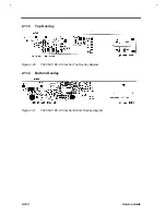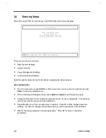
Major Chips Description
2-103
Operation Conditions
•
OPERATING TEMPERATURE
0 TO +50
•
OPERATING HUMIDITY
90% MAX. R.H
•
STORAGE TEMPERATURE
10 TO +85
•
STORAGE HUMIDITY
90% MAX. R.H
•
MTBF
50000 HRS
2.11.2
Pin & Connector Assignment
J1: 52103-1217 (MOLEX)
Table 2-22
Pin Description
PIN NO.
SYMBOL
DESCRIPRION
1
DCBATTIN
DC (7.0V ~ 21.0V)
2
GND
POWER GND
3
CCFTON
PWM SIGNAL FOR ON/OFF AND
BRIGHTNESS CONTROL
4
DATA
ID X24C02 DATA
5
+5.0V
+5.0V
±
10%
6
SGND
LOGIC GND FOR X24C02
7
N.C.
8
CK
CLOCK FOR X24C02
9
N.C.
10
VEE
VEE OUTPUT
11
CTEN
CONTRAST ON/OFF TTL LEVEL
″
H
″
ON
12
CTVREN
PWM SIGNAL FOR CONTRAST VOLTAGE
J2:SM02(8.0)B-BHS-1-TB2P (JST)
Table 2-23
Pin Description
PIN NO.
SYMBOL
DESCRIPRION
1
VOUT1
Lanp , Input HV
2
NC
3
VOUT2
Lanp , Input LV
Summary of Contents for Extensa 61X
Page 6: ...vi ...
Page 26: ...1 8 Service Guide Figure 1 5 Main Board Layout Bottom Side ...
Page 49: ...System Introduction 1 31 1 5 1 3 Power Management Figure 1 14 Power Management Block Diagram ...
Page 55: ...System Introduction 1 37 1 6 System Block Diagram Figure 1 15 System Block Diagram ...
Page 64: ...Major Chips Description 2 7 2 2 5 Pin Diagram Figure 2 4 M1521 Pin Diagram ...
Page 99: ...2 42 Service Guide 2 5 3 Pin Diagram Figure 2 10 C T 65550 Pin Diagram ...
Page 117: ...2 60 Service Guide Figure 2 12 Functional block diagram CardBus Card Interface ...
Page 119: ...2 62 Service Guide Figure 2 14 PCI to CardBus terminal assignments ...
Page 135: ...2 78 Service Guide 2 7 3 Pin Diagram Figure 2 16 NS87336VJG Pin Diagram ...
Page 145: ...2 88 Service Guide 2 8 2 Pin Diagram Figure 2 17 YMF715 Block Diagram ...
Page 185: ...Disassembly and Unit Replacement 4 5 Figure 4 3 Disassembly Sequence Flowchart ...
Page 209: ...B 2 Service Guide ...
Page 210: ...Exploded View Diagram B 3 ...


