


TPU2000/2000R Modbus/Modbus Plus Automation Guide
353
E
C
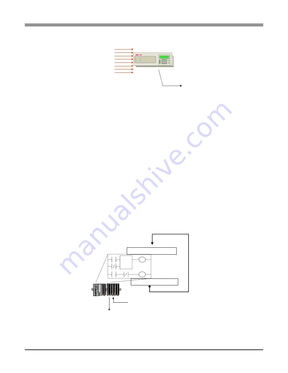
8 Data Slave Paths
Global Data Out
ABB DPU/TPU/GPU 2000R Protective Relay
Figure 2. ABB Protective Relay Path Implementation
Setting the address, of the ABB protective relay is accomplished via the front panel interface or via the ECP
programming software accessible via the programming port. The address is in HEX encoding.
For example, if the PLC in Figure 1 was configured for address 1 and the ABB Protective Relay was configured
for address 10 decimal (or configured as ADDRESS “A” hex through the front panel or ECP), the PLC would
address the relay through one of any of the following addresses:
•
10.1.0.0.0 - Address 10 Path 1
•
10.2.0.0.0 - Address 10 Path 2
•
10.3.0.0.0 - Address 10 Path 3
•
10.4.0.0.0 - Address 10 Path 4
•
10.5.0.0.0 - Address 10 Path 5
•
10.6.0.0.0 - Address 10 Path 6
•
10.7.0.0.0 - Address 10 Path 7
•
10.8.0.0.0 - Address 10 Path 8
The Master Block Explained
The Modicon PLC allows for 4X data retrieval via Modbus Plus. The PLC scans ladder logic as such: Read PLC
INPUTS - Execute LADDER LOGIC Write PLC Outputs. The PLC scan is illustrated in Figure 3. The PLC
reads the physical inputs wired into the unit, executes the program written in the PLC’s native language (icon
based Ladder Logic), and writes the status to the physical Output modules to control the hardwired components.
TMR 0.1
P:
40001
C;
40100
Ladder Logic
PLC
Hardwired
Outputs
(EXAMPLE: Annunciator Lights,
Master Trip Coordination
Trip Contacts ...)
READ Hardwired PLC Input I/O
Write Hardwired Output I/O
PLC
Hardwired
Inputs
(EXAMPLE: Breaker Status, Control
Switch Positions ….)
Figure 3. Typical PLC Logic Execution
Summary of Contents for TPU2000
Page 10: ......