

28
4)
Make necessary bends in tubing to ease installation of the tubing into NGC
and Pressure Regulator.
NOTE:
Tube, Ferrule and Nut should always enter connection perpendicular.
5)
Install reducer into Carrier Gas Regulator.
6)
Insert tube with ferrule into reducer/Pressure Regulator output fitting. Move
Nut down onto ferrule, screw onto fitting and tighten.
7)
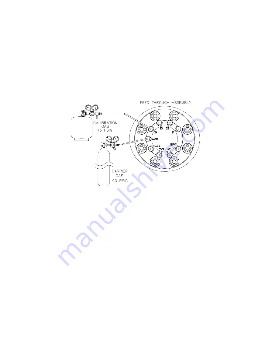
Carrier Gas Pressure should be set at 90 PSIG.
8)
Purge air from the transport tubing by opening the shut-off valve located on
the Regulator.
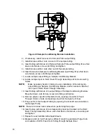
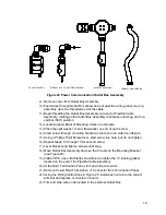
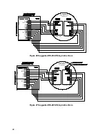
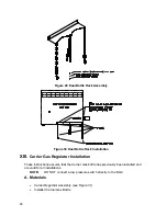
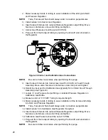
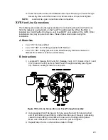
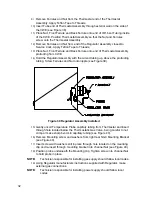
Figure 34 Carrier and Calibration Gas Connections
NOTE:
Be sure to follow local codes when performing this purge.
9)
Insert tube with ferrule into Carrier Gas Input Port (CAR) on Feed-Through
Assembly. Move valco Nut down onto ferrule, screw into port and tighten.
10)
Determine input port for Calibration Gas (typically S4) on NGC Feed-Through
Assembly (see Figure 34).
11)
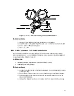
Locate ¼” Low Pressure Output fitting on installed Pressure Regulator on
Calibration Gas Bottle.
12)
Measure and cut 1/16” SST Tubing to required length.
13)
Make necessary bends in tubing to ease installation of the ferrule and tubing
into NGC and Pressure Regulator.
NOTE:
Tube, Ferrule and Nut should always enter connection perpendicular.
14)
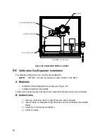
Install reducer into Calibration Gas Regulator if required.
15)
Insert tube with ferrule into reducer/Pressure Regulator output fitting. Move
Nut down onto ferrule, screw onto fitting and tighten.
16)
Calibration Gas Pressure should be set at 15 PSIG.
17)
Purge air from the transport tubing by opening the shut-off valve located on
the Regulator.
NOTE:
Be sure to follow local codes when performing this purge.


