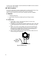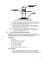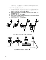
18
B. Instructions
1)
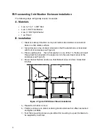
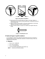
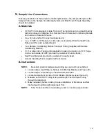
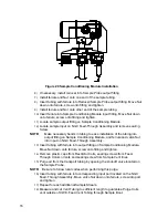
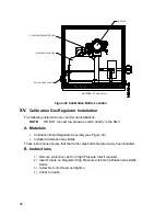
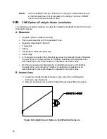
Remove left side access plate from enclosure (see Figure 22).
2)
Gain access to rear Termination Panel by loosening the Countersunk Hex
Socket Locking Set Screw in the rear end cap using a 1/16” Hex wrench, then
unscrewing the end cap.
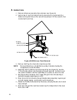
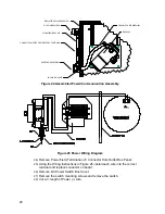
FLEXABLE CABLE
DC POWER SWITCH
OUTLET BOX ASSY
ACCESS OPENING
INTERNAL
CONNECTION ASSY
Figure 22 CWE Access Panel Removed
3)
Remove Hub Plug from the bottom most Access Hub.
NOTE:
Remove Elbow Cap on Outlet Box Assembly to facilitate feeding the
wrapped wire around the elbow.
4)
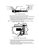
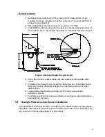
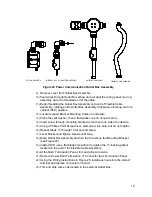
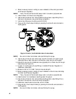
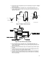
Beginning with the Internal Connection Assembly (see Figure 23), feed the
13” wire bundle (elbow end of assembly) through open hub. Continue to pull
wire past terminations until the nipple fitting is in position to screw into Hub.
5)
Moving assembly Clockwise screw nipple fitting into hub until assembly is
tight and hanging straight down at a 180
.
6)
Feed other end of wire bundle through Flexible Cable Assembly, beginning at
end with Sealing Gasket, until threads meet Conduit Seal.
7)
Rotate the Flexible Cable Assembly Clockwise, screwing threads into Conduit
Seal until tight.
8)
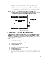
Feed wires through the small hole located near the Sample Boot in the lower
front of the CWE.

