27
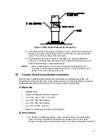
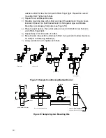
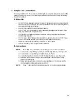
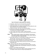
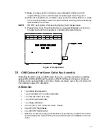
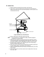
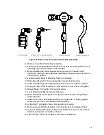
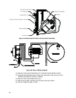
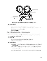
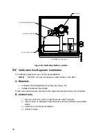
Figure 33 Calibration Gas Pressure Regulator with Relief Valve
XVI.
Carrier Gas and Calibration Gas Connections
The following procedures describe the steps for connecting the external Carrier Gas and
Calibration Gas lines from the respective regulators to the Feed-Through Assembly on
the NGC. They are applicable for both a Meter Run and Cold Weather Enclosure
installation.
A. Materials
•
Installed Carrier Gas Pressure Regulator
•
1/16” SST Chromatography Grade Transport Tubing (Amount to be determined
by technician based on distance from Carrier Gas Bottle Regulator to Sample
Input Filter).
•
Installed Calibration Gas Pressure Regulator
•
1/16” SST Chromatography Grade Transport Tubing (Amount to be determined
by technician based on distance from Calibration Gas Bottle Regulator to Sample
Input Filter).
•
4 ea. 1/16” Ferrule and Nut
•
2 ea. ¼” NPT to 1/16” Reducer or other size as determined from
Carrier/Calibration Gas Regulator.
NOTE:
These instructions assume that the regulators and gas bottles have
previously been installed.
B. Instructions
1)
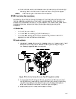
Locate Carrier Gas Input Port (CAR) on NGC Feed-Through Assembly (see
Figure 34).
2)
Locate ¼” Low Pressure Output fitting on installed Pressure Regulator.
3)
Measure and cut 1/16” SST Tubing to required length.

