31
3)
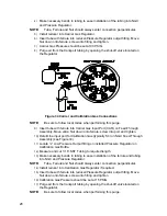
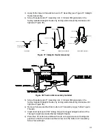
Apply Teflon tape to threads male end of T Assembly (see Figure 37 Catalytic
Heater Assembly).
4)
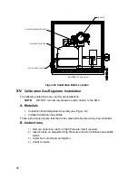
Screw threaded end of T Assembly into ¼” female fitting located on the
factory installed Catalytic Heater, by turning entire Assembly clockwise until
tight (see Figure 38).
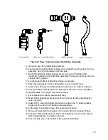
T ASSEMBLY
TUBING
THERMOSTAT ASSEMBLY
REGULATOR ASSEMBLY
REGULATOR
MALE, 3/8 x 1/4 NPT
MALE, 3/8 x 1/4 NPT
1/4 NPT PLUG
3/8" TUBBING
TEMPERATURE PROBE
W/ FERRULES AND NUT
REGULATOR
MALE, 3/8 x 1/4 NPT
SERVICE COCK
THERMOSTAT
Figure 37 Catalytic Heater Assembly
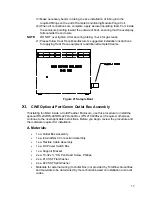
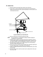
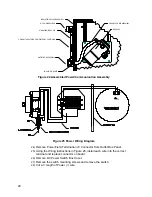
Figure 38 Thermostat Assembly Installed
5)
Screw threaded end of T Assembly into ¼” female fitting located on the
factory installed Catalytic Heater, by turning entire Assembly clockwise until
tight (see Figure 38).
6)
Remove Ferrules and Nut from bottom of T Assembly. Apply Teflon Tape to
Threads.
7)
Insert short bent end of 3/8” tubing closest to longest straight portion of the
Tubing through hole located below Catalytic Heater.
8)
Place Nut, Front Ferrule and Back Ferrule onto opposite end of tubing and
position so that the Ferrules and Nut screw onto the bottom of T Assembly.
Screw Nut until tight.

