background image


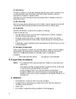
2) Unpacking 

The NGC is shipped in a specially designed shipping carton which contains the unit, 
mounting brackets, parts list and wiring and interconnect diagrams. Optional 
equipment is shipped in a separate carton. 

Carefully remove all internal and external packing material. Carefully remove all 
items from the box. 

3)  Bill of Lading 

After removing protective shipping cover from NGC, compare shipped contents with 
those listed on Bill of Lading. All items should match those on Bill of Lading. 

4) Inspection 

Examine internal NGC components for evidence of damage. 

Points of inspection are: 

  Visually inspect exterior of unit for dents, chipped paint, scratches, damaged 

threads or broken glass plate, etc. 

  Physically inspect rear interior mounted circuit boards, cables, front interior 

mounted circuit boards, for loose cables, boards, display and mounting screws 
etc. 

  If applicable, inspect Calibration/Carrier gas bottles to be certain they are correct 

for the installation. 

5) Damaged Components 

If there is any damage, or if there are noticeable defects, notify your local Totalflow 
representative. Keep all shipping materials as evidence of damage, for carriers 
inspection. Totalflow will arrange for immediate repair or replacement. 

Telephone: 

USA: (800) 442-3097 toll free           International: 1-918-338-4880 

II. 

Sample Probe Installation 

NOTE:


1) If a Sample Probe has previously been installed, you may skip these 
instructions. 


2) Sample Probe Pipe coupling should be located on the top of the meter 
run and may be mounted vertical or horizontal. 


3) If the Sample Probe is to be located inside the Cold Weather 
Enclosure, it MUST be a vertical mounting on a horizontal pipe and be 
installed on the meter run prior to seating the Cold Weather Enclosure on 
the meter run. 

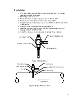
A. Materials 

  Horizontal Pipe Coupling ¾” NPT (previously installed) 

  Sample Probe (Configuration to be determined by the technician based on 

installation and local codes.) 

 Teflon 

Tape 

  Or Customer supplied Pipe Dope (suitable for chromatography) 

Summary of Contents for Totalflow Cold Weather Enclosure

Page 1: ...A TOTALFLOW Cold Weather Enclosure and Equipment Installation for use with NGC8200 Manual ABB Inc Totalflow Products 7051 Industrial Blvd Bartlesville Oklahoma 74006 Tel USA 800 442 3097 International 1 918 338 4880 ...

Page 2: ...ranslated versions in any other language shall be maintained as accurately as possible Should any discrepancies exist the US English version will be considered final Notice This publication is for information only The contents are subject to change without notice and should not be construed as a commitment representation warranty or guarantee of any method product or device by Owner Inquiries rega...

Page 3: ...I NGC Installation 12 IX Sample Conditioning Module Installation 13 X Sample Line Connections 15 XI CWE Optional Pwr Comm Outlet Box Assembly 17 XII CWE Carrier Gas Bottle Rack Installation 23 XIII Carrier Gas Regulator Installation 24 XIV CWE Calibration Gas Bottle Installation 25 XV Calibration Gas Regulator Installation 26 XVI Carrier Gas and Calibration Gas Connections 27 XVII Vent Line Connec...

Page 4: ... Access Panel Removed 18 Figure 23 Power Communication Outlet Box Assembly 19 Figure 24 Assembled Power Communication Assembly 20 Figure 25 Power Wiring Diagram 20 Figure 26 Suggested RS 232 Wiring Instructions 22 Figure 27 Suggested RS 485 Wiring Instructions 22 Figure 28 Suggested RS 422 Wiring Instructions 23 Figure 29 Dual Bottle Rack Assembly 24 Figure 30 Dual Bottle Rack Installation 24 Figu...

Page 5: ...ous areas as required C Figure 1 Typical Cold Weather Enclosure with Electric Heater Locating Area for Installation The NGC should be located as close as possible to the Sample Probe installation point This prevents the need for high gas flow rates through sample lines to assure analysis accuracy of current sample If there is more than one stream being analyzed locate the NGC in a central location...

Page 6: ...on Carrier gas bottles to be certain they are correct for the installation 5 Damaged Components If there is any damage or if there are noticeable defects notify your local Totalflow representative Keep all shipping materials as evidence of damage for carriers inspection Totalflow will arrange for immediate repair or replacement Telephone USA 800 442 3097 toll free International 1 918 338 4880 II S...

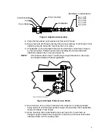
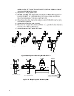
Page 7: ...p or cover NPT threads of Sample Probe see Figure 2 6 Insert gas probe into pipeline coupling see Figure 3 7 Using the correct tool tighten probe Securely tighten so there is no gas leakage DO NOT OVERTIGHTEN 8 Install Shut off valve on secondary side of Sample Probe if desired THREADED NECK 3 4 NPT PRESSURE RELEIVE VALVE PRESSURE GUAGE 1 4 OUTLET PORT Figure 2 Sample Probe 3 4 NPT GAS FLOW SAMPLE...

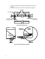
Page 8: ...rizontal with front of enclosure see Figure 4 3 Place a split washer then a flat washer on one of the 1 Bolts and insert through bolt hole located in the angle iron into the outermost corner of the enclosure see Figure 5 4 Move channel Nut into position so that Bolt will screw into Nut Screw Bolt into Nut Figure 4 Typical CWE Stand Mount Installation 5 Repeat for all other corners 6 Position enclo...

Page 9: ...on bottom of upside down enclosure being sure the side with the holes is facing the bottom of the enclosure and the solid sides of the angle iron are facing each other Angle iron should be spaced so that the diameter of the pipe will fit in between 2 Place a split washer then a flat washer on one of the 1 Bolts see Figure 7 3 Insert the Bolt through one of the slotted holes located in the angle ir...

Page 10: ...e 8 8 Insert All Thread through round hole on adjustment side of angle iron 2 1 2 STK 50 1 12 4 12 34 000 43 00 1 00 1 25 BOLT HOLES 87 87 CHAIN HOLE CHAIN RETAINER MOUNTING HOLE ADJUSTMENT ASSEMBLY HOLE Figure 6 Mounting Brackets 31 00 Figure 7 Mounting Hardware Installation ...

Page 11: ...ng the 6 Phillips head screws and lifting the Access Plate with attached insulation from hole see Figure 9 NOTE Lift enclosure above meter run allowing enough clearance to clear pipe and installed Sample Probe if applicable SAMPLE PROBE ACCESS PLATES Figure 9 Sample Probe Access Plates 12 Set enclosure on top of pipe in between the angle iron mounting brackets being careful to insert sample probe ...

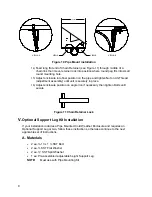
Page 12: ... until unit is securely in place 16 Adjust enclosure position on angle iron if necessary then tighten Bolts until secure Figure 11 Chain Retainer Lock V Optional Support Leg Kit Installation If your installation includes a Pipe Mounted Cold Weather Enclosure and requires an Optional Support Leg or two follow these instructions otherwise continue to the next applicable set of instructions A Materia...

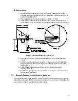
Page 13: ...o Nut but leave loose for later adjustment Repeat for other corner 5 If installing two Support Legs repeat for other angle iron Final tightening of Bolts may be done after support leg s are in desired positioned on a flat stable surface 6 Loosen Adjustment Handle and drop Leg Foot down and retighten Adjustment Handle 7 Foot Plate mounting holes are pre drilled for mounting to a pad Hardware to be ...

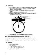
Page 14: ...LATION AEROSOL CAN MASK FRONT OF GAUGE PRIOR TO APPLICATION PRESSURE RELEIF VALVE COLD WEATHER ENCLOSURE PLUG PLATE INSULATION PLUG Figure 13 Installed Sample Probe and Access Plate Insulation VII Cold Weather Enclosure CWE Mounting Plate If you will be installing an NGC inside a Cold Weather Enclosure use this procedure to install the mounting plate inside the enclosure otherwise continue to the ...

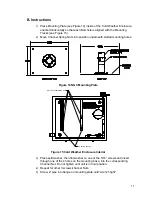
Page 15: ...tted mounting holes Figure 14 NGC Mounting Plate MOUNTING TRACKS 5 16 18 CHANNEL SPRING NUTS Figure 15 Cold Weather Enclosure Interior 3 Place split washer then flat washer on one of the 5 16 screws and insert through one of the 4 holes on the mounting base into the corresponding Channel Nut Do not tighten until unit is in final position 4 Repeat for other 3 screws channel Nuts 5 Screw 2 pipe into...

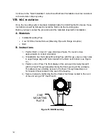
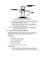
Page 16: ...ctions 1 Position NGC on top of 2 pipe stand see Figure 16 level in close approximation to correct orientation 2 If installation has the Optional Mounting Pipe with Flange ensure screw holes in upper flange align with holes located in the NGC neck bottom see Figure 17 3 Position unit on Pipe The front display of the unit would normally face left with the Feed Through Assembly facing the front open...

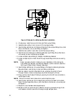
Page 17: ...s to the rear end cap of the unit IX Sample Conditioning Module Installation Both Sample Conditioning Module Mounting Brackets are installed identically The Single Module Bracket will hold a single stream Sample Conditioning Module while the Multiple Module Bracket will hold up to 3 Sample Conditioning Modules A Materials Installed NGC Single or Multiple Module Mounting Kit 1 ea 312 x 2 5 x 3 62 x...

Page 18: ... flat washer on end of U Bolt Screw Nut onto end of Bolt finger tight 5 Repeat Step 4 for other side of U Bolt 6 Move bracket into position underneath NGC being careful to allow clearance for Sample Conditioning Module s 7 Using a socket wrench tighten both Nuts 2102023 001 2102023 002 2102024 001 2102024 002 Figure 18 Sample Conditioning Module Bracket 2 Pipe U Bolt VIEW A A A A A A B B VIEW B B ...

Page 19: ...ioning Module 1 16 or larger Vent Tubing and materials for making connection to 1 16 Purge Coil to vent outside of CWE provided by customer for each stream Heat Trace Materials provided by customer for each stream Aerosol Insulating Foam supplied with enclosure B Instructions NOTE Be certain ends of stainless steel tubing are open and not restricted 1 Locate sample input fitting on Sample Conditio...

Page 20: ... tubing into output fitting on Sample Conditioning Module and ferrule and valco Nut into input on NGC Feed Through Assembly 13 Insert tubing with ferrule into output fitting on Sample Conditioning Module Move Nut down onto ferrule screw onto fitting and tighten 14 Remove plastic caps from Restrictor Coils sealing screws from Feed Through Column Vents and sealing screw from Sample Vent lines 15 Pur...

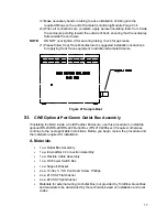
Page 21: ...mple Boot XI CWE Optional Pwr Comm Outlet Box Assembly If installing the NGC inside a Cold Weather Enclosure use this procedure to install the optional RS 232 RS 485 RS 422 Outlet Box P N 2102296 xxx if required otherwise continue to the next applicable instructions Before you begin review the procedure and the materials required for installation A Materials 1 ea Outlet Box Assembly 1 ea Internal ...

Page 22: ...wrapped wire around the elbow 4 Beginning with the Internal Connection Assembly see Figure 23 feed the 13 wire bundle elbow end of assembly through open hub Continue to pull wire past terminations until the nipple fitting is in position to screw into Hub 5 Moving assembly Clockwise screw nipple fitting into hub until assembly is tight and hanging straight down at a 180 6 Feed other end of wire bun...

Page 23: ...f each screw 14 Insert screw through mounting bracket and into hole on side of enclosure 15 Using a Phillips Point Screwdriver start screw into hole but do not tighten 16 Repeat Steps 13 through 15 for second screw 17 Level bracket and tighten screws until snug 18 Move Outlet Box Assembly down so that it rests on the Mounting Bracket see Figure 24 19 Inside CWE use a flat blade screwdriver to tigh...

Page 24: ...d Power Communication Assembly POWER D1 J1 Figure 25 Power Wiring Diagram 24 Remove Power Field Termination J3 Connector from Outlet Box Panel 25 Using the Wiring Instructions in Figure 25 install each wire into the correct terminal and replace connector on board 26 Remove DC Power Switch Box Cover 27 Remove the switch mounting screws and remove the switch 28 Cut a 3 length of Power wire ...

Page 25: ... DC Power Switch 38 Using the Wiring Instructions in Figure 25 wire Power to upper terminal screw and tighten 39 Bring new Power wire into Power Switch Enclosure and pull short length out to allow wiring 40 Using the Wiring Instructions in Figure 25 wire new Power length to bottom terminal screw and tighten 41 Re install DC Power Switch into box 42 Using the Wiring Instructions in Figure 26 RS 232...

Page 26: ...COMM PORT 2 1 6 7 8 9 1 2 3 J11 RXD TXD RTS CTS GND SW PWR Figure 26 Suggested RS 232 Wiring Instructions 5 3 4 2 J10 COMM PORT 2 1 6 7 8 9 BUS BUS RRTS GND SW PWR TERMINATION BOARD NGC 8200 2102080 XXX 1 2 3 J9 1 2 3 J11 5 3 4 2 J8 COMM PORT 1 1 BUS BUS RRTS GND 8 8 10 10 9 9 11 11 12 12 6 7 8 9 3 3 5 5 4 4 6 6 7 7 1 1 2 2 SW PWR COMM 1 COMM 2 Figure 27 Suggested RS 485 Wiring Instructions ...

Page 27: ...uld be installed on each gas bottle see Figure 29 A Materials 1 ea Bracket with Chain Assembly attached 2 ea 3 8 16 x 5 8 SST Hex Head Bolt 2 ea 3 8 SST Split Washers 2 ea 3 8 SST Flat Washers B Instructions 1 Place a split washer then a flat washer on one of the 5 8 Bolts and insert through bolt hole located in the Bottle Rack Bracket into the corresponding hole located along the bottom edge of t...

Page 28: ...r Gas Regulator Installation These instructions assume that the Carrier Gas bottle has previously been installed and are valid for all installations NOTE DO NOT connect a low pressure switch directly to the NGC A Materials Carrier Regulator Assembly see Figure 31 Installed Carrier Gas Bottle ...

Page 29: ... Bottle when located inside of the Cold Weather Enclosure A gas regulator should be installed on each gas bottle Refer to Figure 32 A Materials Strapping material shipped with Cold Weather Enclosure Calibration Gas Blend Bottle B Instructions 1 Locate the bottle bracket in the right front area of the Cold Weather Enclosure see Figure 32 2 Set Calibration bottle inside of enclosure situated against...

Page 30: ...OT connect low pressure switch directly to the NGC A Materials Calibration Blend Regulator Assembly see Figure 33 Installed Calibration Gas Bottle These instructions assume that the Carrier Gas bottle has previously been installed B Instructions 1 Remove protective cap from High Pressure Inlet if required 2 Insert Ferrule on Regulator High Pressure Inlet into Calibration Gas Bottle Outlet 3 Screw ...

Page 31: ...based on distance from Carrier Gas Bottle Regulator to Sample Input Filter Installed Calibration Gas Pressure Regulator 1 16 SST Chromatography Grade Transport Tubing Amount to be determined by technician based on distance from Calibration Gas Bottle Regulator to Sample Input Filter 4 ea 1 16 Ferrule and Nut 2 ea NPT to 1 16 Reducer or other size as determined from Carrier Calibration Gas Regulato...

Page 32: ... valco Nut down onto ferrule screw into port and tighten 10 Determine input port for Calibration Gas typically S4 on NGC Feed Through Assembly see Figure 34 11 Locate Low Pressure Output fitting on installed Pressure Regulator on Calibration Gas Bottle 12 Measure and cut 1 16 SST Tubing to required length 13 Make necessary bends in tubing to ease installation of the ferrule and tubing into NGC and...

Page 33: ...aterials 4 ea 1 16 Ferrule and Nut 4 ea 1 16 SST Vent Tubing supplied with NGC or 4 ea 1 16 SST Tubing Amount to be determined by technician based on distance from NGC to external vent location B Instructions 1 Locate GPV Gauge Port Vent SV Sample Vent CV1 Column Vent 1 and CV2 Column Vent 2 ports on NGC Feed Through Assembly see Figure 35 Remove sealing screws for vent ports Figure 35 Vent Line C...

Page 34: ...nting Clip Teflon Tape male pipe connection from External gas source to Catalytic Heater Materials for gas source is not be provided by Totalflow Quantities and materials to be determined by the technician based on installation and local codes DC Power source wiring Materials for external Power source for Electrical Preheat wiring not provided by Totalflow Quantities and materials to be determined...

Page 35: ...4 NPT SERVICE COCK THERMOSTAT Figure 37 Catalytic Heater Assembly Figure 38 Thermostat Assembly Installed 5 Screw threaded end of T Assembly into female fitting located on the factory installed Catalytic Heater by turning entire Assembly clockwise until tight see Figure 38 6 Remove Ferrules and Nut from bottom of T Assembly Apply Teflon Tape to Threads 7 Insert short bent end of 3 8 tubing closest...

Page 36: ...rules and Nut onto nipple see Figure 39 Figure 39 Regulator Assembly Installed 15 Gently uncoil Temperature Probe capillary tubing from Thermostat and insert through hole located below the Thermostatic Gas Valve being careful to not crimp or make sharp bends in capillary tubing see Figure 40 16 Remove Mounting screw and washers from right rear NGC Mounting Bracket see Figure 40 17 Insert screw wit...

Page 37: ...E Optional Electric Heater Installation The following procedures describe the steps for wiring an Electric Heater for the Cold Weather Enclosure A Materials Electric Heater Option Factory Installed see Figure 42 AC Power source wiring Materials for external Power source for Electric Heater wiring not provided by Totalflow Quantities and materials to be determined by the technician based on install...

Page 38: ...0 VAC or HEATER 400 WATT 230 VAC THERMOSTAT SAMPLE PROBE OPTION C Figure 42 Electric Heater Installed in CWE B Instructions 1 Using the wiring instructions shown in Figure 43 and Manufacturers Instructions enclosed with Heater make external connections Figure 43 Electric Heater Option Wiring Instructions ...

Page 39: ...des a Solar Panel connected to a Battery Plug in Charger Regulator battery connector 2 Test power using a Multi Meter connected to J1 terminals of Phoenix Connector to determine if DC voltage is between 10 5 and 16 0 volts During Startup operations unit will draw a minimum of 13 8 VDC 3 If volts are within range the power should be disconnected Phoenix Connector inserted into Termination Panel J1 ...

Page 40: ...36 B B BL L LA A AN N NK K K P P PA A AG G GE E E ...

Reviews: