15
X.
Sample Line Connections
Following installation of the Sample Conditioning Module(s), the sample tubing from the
Sample Probe to the Sample Conditioning System and NGC Feed-Through Assembly
should be installed.
A. Materials
•
1/8” SST Chromatography Grade Transport Tubing (Amount to be determined by
technician based on distance from Sample Probe to Sample Conditioning Module
and number of Sample Streams.
•
2 ea. Ferrule and Nut (for each sample stream)
•
1 ea. ¼” NPT to 1/8” Reducer or other size as determined from Sample Probe
Output port (for each sample stream)
•
1 ea. Sample Conditioning Module Transport Tubing (supplied with Sample
Conditioning Module).
•
1/16” or larger Vent Tubing and materials for making connection to 1/16” Purge
Coil to vent outside of CWE (provided by customer for each stream)
•
Heat Trace Materials provided by customer for each stream
•
Aerosol Insulating Foam (supplied with enclosure)
B. Instructions
NOTE:
Be certain ends of stainless steel tubing are open and not restricted.
1)
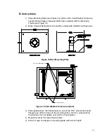
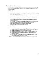
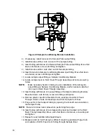
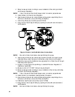
Locate sample input fitting on Sample Conditioning Module (see Figure 20).
2)
Locate sample output fitting on installed Sample Probe.
3)
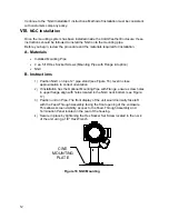
Locate Sample Boot on side of Cold Weather Enclosure (see Figure 21).
4)
Measure and cut SST Tubing to required length. Feed Sample Tubing
through Sample Boot.
5)
Make necessary bends in tubing to ease installation of the ferrule and Nut
into Sample Conditioning Module Input Port.
NOTE:
Tube, Ferrule and Nut should always enter connection perpendicular.

