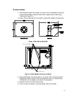
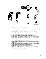

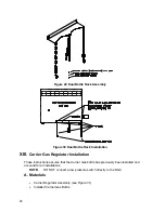
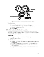
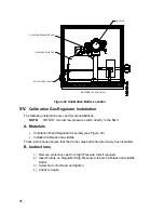

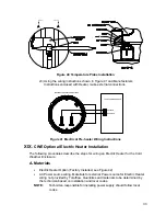

21
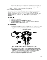
NOTES: Optionally, Communication wires maybe run directly to the spare Conduit
Hub located on the bottom of the Outlet Box Assembly. Please follow
local codes.
For the purpose of this manual, we will assume that communication wiring
will be included with the power wiring in one conduit run.
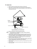
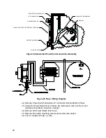
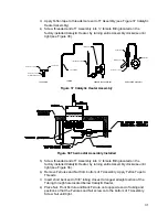
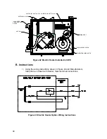
29)
Tape 3’ Power (+) wire, Ground and Communication wire ends together.
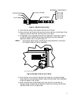
30)
Feed through Conduit Hub located on the bottom of the DC Power Switch
Box, past cover opening, around elbow and out.
31)
Continue pulling wire until approximately 2’ of wire is extending out of the DC
Power Switch Box.
NOTE:
Be careful to not pull 3’ Power (+) wire past the DC Power Switch Box
opening.
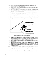
32)
Feed excess wire through 6” Nipple Fitting, Conduit Seal, 5” Nipple Fitting
and out into Outlet Box opening. Pull sufficient wire to complete field wiring.
33)
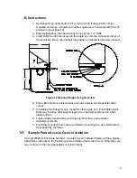
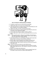
Remove Power Field Termination J4 Connector from Outlet Box Panel.
34)
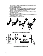
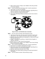
Using the Wiring Instructions in Figure 25, install power (+) and power (-)
wires into the correct terminal pins and replace connector on board.
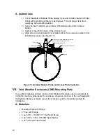
35)
Holding wires, slide DC Power Switch box up to 6” nipple fitting on end out
Outlet Box Assembly.
36)
Slide Conduit Union onto end of nipple fitting and screw on.
37)
Loosen terminal screws on DC Power Switch.
38)
Using the Wiring Instructions in Figure 25, wire Power (+) to upper terminal
screw and tighten.
39)
Bring new Power (+) wire into Power Switch Enclosure and pull short length
out to allow wiring.
40)
Using the Wiring Instructions in Figure 25, wire new Power (+) length to
bottom terminal screw and tighten.
41)
Re-install DC Power Switch into box.
42)
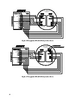
Using the Wiring Instructions in Figure 26 (RS-232), Figure 27 (RS-485) or
Figure 28 (RS-422), make field connections to plug NGC Termination Panel
Com Port (s) , re-insert into corresponding connector in Termination Panel.
43)
Using the Wiring Instructions in Figure 26 (RS-232), Figure 27 (RS-485) or
Figure 28 (RS-422), make field connections to plug J1, re-insert into
corresponding connector in Outlet Box.
44)
Using the Wiring Instructions in Figure 25 (RS-232), Figure 27 (RS-485) or
Figure 28 (RS-422), make field connections to plug J2, re-insert into
corresponding connector in Outlet Box.
NOTES: Communication wiring terminations inside the Power/Communication
Outlet Box Assembly are pass-through connections, meaning that J1-pin
1 is associated with J2-pin 1. Therefore, pin outs may be user defined
and wiring Instructions for this assembly are only suggestions.
External wiring and connections should be performed by an experienced
technician and follow local codes.
45)
Following instructions included with unit, complete seal between DC Power
Switch and Outlet Box Assembly.