


32
9)
Remove Ferrules and Nut from the Thermostat end of the Thermostat
Assembly. Apply Teflon Tape to Threads.
10)
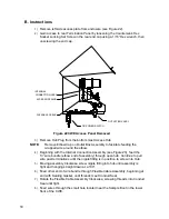
Insert Tube end of Thermostat Assembly through exterior wall on the side of
the CWE (see Figure 38).
11)
Place Nut, Front Ferrule and Back Ferrule onto end of 3/8” bent Tubing inside
of the CWE. Position Thermostat Assembly so that the Nut and Ferrules
screw onto the Thermostat Assembly.
12)
Remove Ferrules and Nut from end of the Regulator Assembly closest to
Service Cock. Apply Teflon Tape to Threads.
13)
Place Nut, Front Ferrule and Back Ferrule onto end of Thermostat Assembly
protruding from CWE.
14)
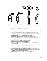
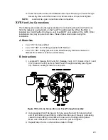
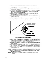
Hold the Regulator Assembly with the curved tubing up, above the protruding
tubing. Screw Ferrules and Nut onto nipple (see Figure 39).
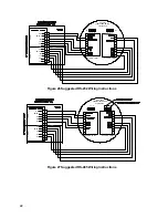
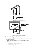
Figure 39 Regulator Assembly Installed
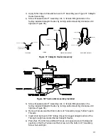
15)
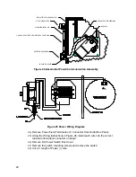
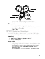
Gently uncoil Temperature Probe capillary tubing from Thermostat and insert
through hole located below the Thermostatic Gas Valve, being careful to not
crimp or make sharp bends in capillary tubing (see Figure 40).
16)
Remove Mounting screw and washers from right rear NGC Mounting Bracket
(see Figure 40).
17)
Insert screw with washers still in place through hole located on the mounting
clip and re-insert through mounting bracket into channel Nut (see Figure 40).
18)
Position probe underneath the Mounting clip. Tighten screw into channel Nut
to hold probe in place.
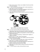
NOTE:
Technician responsible for installing gas supply should follow local codes.
19)
Using Regulator manufacturers instructions supplied with Regulator, make
external gas connections.
NOTE:
Technician responsible for installing power supply should follow local
codes.


