


19
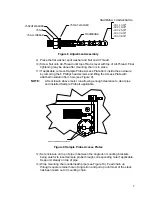
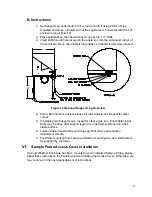
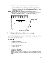
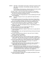
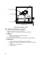
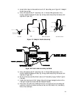
DC POWER SWITCH
INTERNAL NGC CONNECTION ASSEMBLY
FLEXIBLE CABLE ASSEMBLY
OUTLET BOX ASSEMBLY
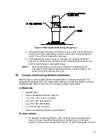
Figure 23 Power Communication Outlet Box Assembly
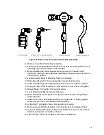
9)
Remove cover from Outlet Box Assembly.
10)
Feed wires through Outlet Box elbow and out past the wiring panel, moving
assembly up to the threaded end of the cable.
11)
Begin threading the Outlet Box Assembly onto end of Flexible Cable
Assembly, rotating entire Outlet Box Assembly Clockwise until snug and in a
vertical (360
) position.
12)
Locate Support Bracket Mounting Holes on enclosure.
13)
Place the split washer, then a flat washer on end of each screw.
14)
Insert screw through mounting bracket and into hole on side of enclosure.
15)
Using a Phillips Point Screwdriver, start screw into hole, but do not tighten.
16)
Repeat Steps 13 through 15 for second screw.
17)
Level bracket and tighten screws until snug.
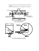
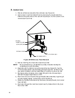
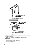
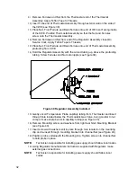
18)
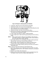
Move Outlet Box Assembly down so that it rests on the Mounting Bracket
(see Figure 24).
19)
Inside CWE, use a flat blade screwdriver to tighten the ¾” locking gasket
located on the end of the Flexible Cable Assembly.
20)
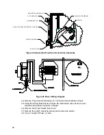
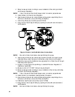
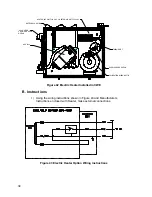
At the NGC Termination Panel, trim and strip wire ends.
21)
Remove Power Field Termination J1 Connector from Termination Panel.
22)
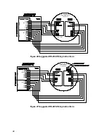
Using the Wiring Instructions in Figure 25, install each wire into the correct
terminal and replace connector on board.
23)
Trim and strip wire ends located in the external Outlet Box.


