


20
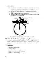
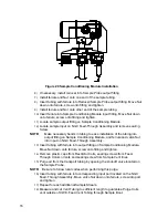
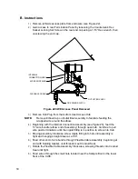
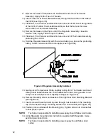
NGC8200
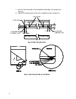
INSULATED ENCLSOSURE WALL
MOUNTING BRACKET
LOCKING GASKET
FLEXABLE CABLE ASSEMBLY
DC POWER SWITCH
OUTLET BOX ASSEMBLY
CONDUIT SEAL-TO BE COMPLETED BY CUSTOMER
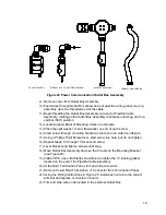
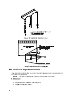
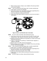
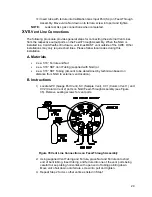
Figure 24 Assembled Power/Communication Assembly
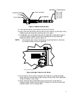
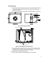
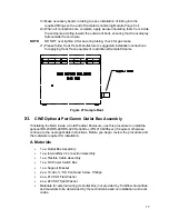
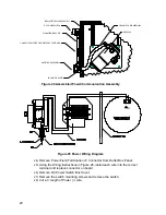
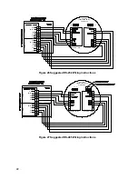
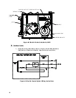
POWER
D1
J1
(-)
(+)
Figure 25 Power Wiring Diagram
24)
Remove Power Field Termination J3 Connector from Outlet Box Panel.
25)
Using the Wiring Instructions in Figure 25, install each wire into the correct
terminal and replace connector on board.
26)
Remove DC Power Switch Box Cover.
27)
Remove the switch mounting screws and remove the switch.
28)
Cut a 3’ length of Power (+) wire.


