

UNITY
CODE X
ARGB MIDI TOWER CASE
U S E R M A N U A L
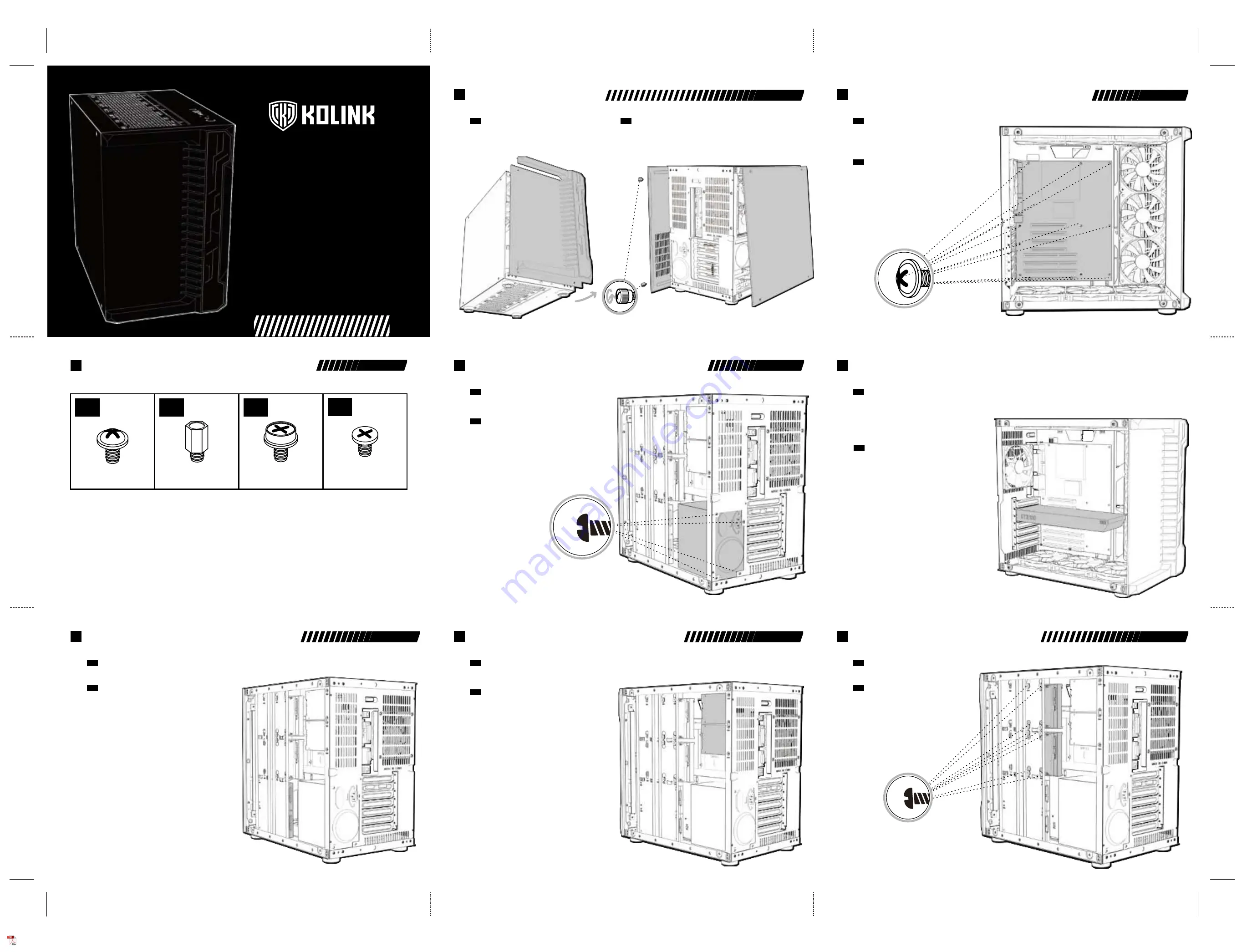
• Remove the left side panel by removing the four thumbscrews and lifting the glass panel away.
• Remove the right side panel by removing the two rear thrumbscrews and sliding the panel backwards.
• To remove the front panel, remove the right hand side plastic panel first (being careful with
the I/O wiring) and unscrew the two screws on the glass panel, before lifting away from the chassis.
PANEL REMOVAL
EN
• Entfernen Sie das linke Seitenteil, indem Sie die vier Rändelschrauben und heben Sie das Paneel ab.
• Entfernen Sie das rechte Seitenteil, indem Sie die beiden rückwärtigen Rändelschrauben
entfernen und das Paneel nach hinten ziehen.
• Um die Front zu entfernen, lösen Sie zunächst vorsichtig die rechte Kunststoffabdeckung ab. Achten Sie
dabei auf die Verkabelung. Anschließen entfernen Sie die beiden Schrauben und heben Sie das Temperglaspaneel ab.
ENTFERNEN DER SEITENTEILE
DE
• Align your motherboard with the chassis to locate where the stand-offs should be installed.
Once done, remove the motherboard and fasten stand-offs accordingly.
• Insert your motherboard I/O plate into the cutout at the rear of the case.
• Place your motherboard into the chassis, making sure the rear ports fit into the I/O plate.
• Use the provided motherboard screws to attach your motherboard to the chassis.
MOTHERBOARD INSTALLATION
EN
• Richten Sie Ihr Mainboard im Gehäuse aus, um festzustellen, wo die
Abstandshalter befestigt werden sollen. Entfernen Sie anschließend das
Mainboard und verschrauben Sie die Abstandshalter an den vermerkten Stellen.
• Befestigen Sie das I/O-Shield ihres Mainboards im Ausschnitt an der
Rückseite des Gehäuses.
• Platzieren Sie Ihr Motherboard im Gehäuse und achten Sie darauf, dass die
hinteren Anschlüsse in das I/O-Shield passen.
• Verwenden Sie die mitgelieferten Schrauben Ihres Mainboards, um es an den
Abstandshaltern im Gehäuse zu befestigen.
MAINBOARD INSTALLATION
DE
• Remove the rear PCI-E slot covers as necessary (depending on the slot size of your card)
• Carefully position and slide your PCI-E card into place,
then secure with the add-on card screws supplied.
• If mounting vertically, attach the provided vertical GPU bracket to the PSU shroud, secure
your Kolink PCI-E riser cable to it (sold separately) and attach the cable to the motherboard.
Remove the rear PCI-E slot covers as necessary, then carefully position your PCI-E card,
slot into the PCI-E riser mount and secure with the add-on screws supplied.
VIDEO CARD/PCI-E
CARD INSTALLATION
EN
• Entfernen Sie die PCI-Slotblenden an der Rückseite entsprechend der Größe ihrer Grafikkarte.
• Richten Sie ihre Grafikkarte am Mainboard aus und drücken Sie sie vorsichtig in den
entsprechenden Slot. Befestigen Sie die Grafikkarte mit den entsprecheden Schrauben an
der Rückseite des Gehäuses.
• Bei einer vertikalen Installation befestigen Sie zunächst die mitgelieferte Halterung an
der Netzteilabdeckung und befestigen Sie die optionale Riser-Karte dort und an ihrer
Grafikkarte. Entfernen Sie die entsprechenden PCI-Slotblenden, richten Sie die
Grafikkarte vorsichtig aus und befestigen Sie sie mit den mitgelieferten Scharuben.
INSTALLATION DER
GRAFIKKARTE/PCI-E-KARTE
DE
PANEL REMOVAL
2
MOTHERBOARD INSTALLATION
3
GRAPHICS CARD/PCI-E CARD INSTALLATION
5
POWER SUPPLY INSTALLATION
4
• Platzieren Sie das Netzteil an der unteren rechten Seite des Gehäuses
unter der Netzteilabdeckung.
• Richten Sie die Bohrungen des Netzteils an der Rückseite des Gehäuses
aus und befestigen Sie es mit Schrauben.
INSTALLATION DES NETZTEILS
DE
• Place PSU in the bottom rear right side of the case, within the rear chamber.
• Align the holes and secure with screws.
POWER SUPPLY INSTALLATION
EN
• Befestigen Sie das Laufwerk am Bracket mit Hilfe der beiliegenden
Schrauben und Gummitüllen.
3.5" HDD-INSTALLATION
DE
• Mount your HDD to the bracket using the supplied screws and rubber grommets.
3.5" HDD INSTALLATION
EN
3.5" HDD INSTALLATION
8
• Befestigen Sie das Laufwerk unten an dem HDD-/SSD-Bracket mit Schrauben.
2.5" SSD-INSTALLATION (RÜCKSEITE)
DE
• Mount your SSD's onto the bottom of the HDD/SSD bracket and secure using screws.
2.5" SSD INSTALLATION (REAR)
EN
2.5" SDD INSTALLATION (R)
6
2.5" SDD INSTALLATION (R)
7
• Richten Sie die Bohrungen des Laufwerks oben rechts der Rückseite des Laufwerks und
befestigen Sie es mit Schrauben. Beachten Sie, dass pro Laufwerk nur zwei
Schrauben benötigt werden.
2.5" SSD-INSTALLATION (RÜCKSEITE)
DE
• Align the 2.5" HDD/SSD with the screw holes on the top right hand side of the rear of the chassis
and mount using screws (please note, only 2 screws can be used to mount the SSD's in this position)
2.5" SSD INSTALLATION (REAR)
EN
ACCESSORY PACK CONTENTS
1
x10
x1
x4
x5
Motherboard/SSD Screws
Motherboard Stand-off
3.5” Drive Screw
PSU Screw


