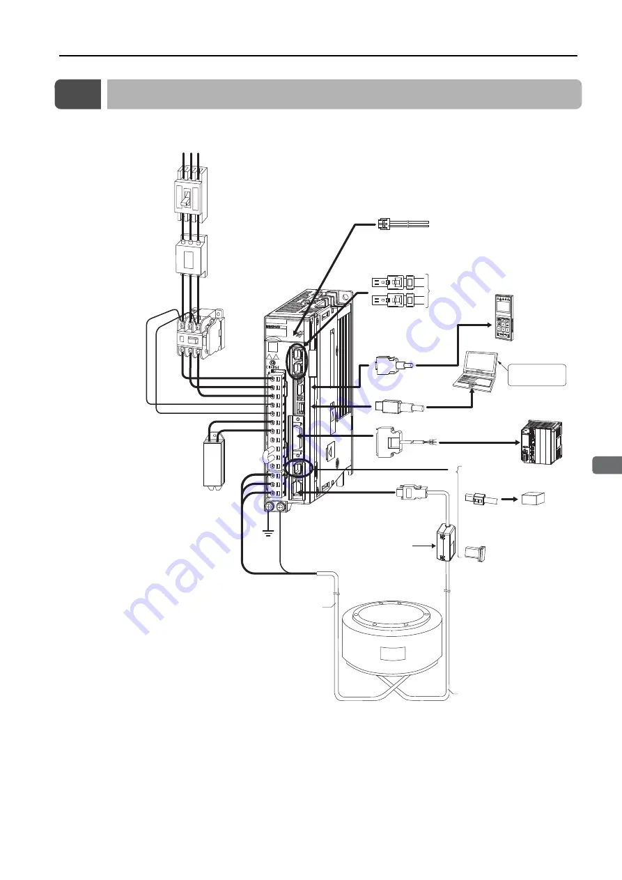
1.2 Configuration with a Direct Drive Servomotor
1-3
1
Peripheral Device
s
and
S
y
s
tem Configuration
s
1.2
Configuration with a Direct Drive Servomotor
*1.
The peripheral devices are described using a MECHATROLINK-III Communications Reference SERVOPACK for
a three-phase 200-VAC power supply input as an example. The shapes of the connectors and pin layout may
be different for SERVOPACKs with other power supply input specifications and for other interfaces.
*2.
The connected devices depend on the interface.
For MECHATROLINK-II communications references: Other MECHATROLINK-II stations
For analog voltage/pulse train references: There is no CN6 connector.
External Regenerative
Re
s
i
s
tor
Noi
s
e Filter
Molded-ca
s
e
circuit breaker
Magnetic Contactor
I/O
S
ignal Cable
S
ERVOPACK
*1
Power
s
upply
Three-pha
s
e, 200 VAC
*1
R
S
T
Computer Cable
External
Regenerative
Re
s
i
s
tor
Cable
Control Power
S
upply Cable
Digital Operator
(JU
S
P-OP05A-1-E)
Digital Operator
cable
Ho
s
t controller
MECHATROLINK Communication
s
Cable
*1
To next
MECHATROLINK-III
s
tation
*2
C
N
6
S
afety Function Device Cable
S
afety function device
S
ERVOPACK
main circuit wire
s
S
ervomotor Main
Circuit Cable
Direct Drive
S
ervomotor
Encoder Cable
Analog Monitor Cable
Computer
Battery Ca
s
e (Required when
an ab
s
olute encoder i
s
u
s
ed.)
When not u
s
ing a
s
afety function,
leave the
S
afety Jumper Connector
connected to the
S
ERVOPACK.
Ground
cable
Engineering
Tool
(pages 10-14, 10-17 and 10-20)
Surge Absorbers (page 12-31)
Reactors (page 12-28)


