TROUBLESHOOTING
9-3
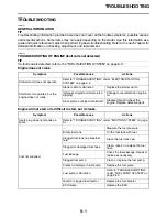
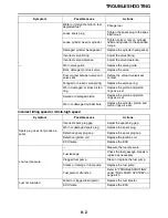
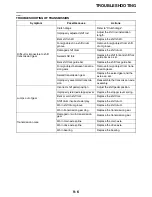
Excessive noise from engine
—
Worn camshaft lobe
Replace the camshaft.
Water or foreign material in fuel,
degraded fuel
Change fuel.
Contaminated throttle body or
clogged internal passage
Clean the throttle body.
Incorrectly adjusted throttle cable
Adjust the throttle grip free play.
Incorrectly adjusted idling speed
(idle screw)
Adjust the idle screw.
Incorrect throttle position sensor
angle
Adjust the throttle position sensor
angle.
Incorrect acceleration position
sensor angle
Adjust the acceleration position
sensor angle.
Faulty ECU
Replace the ECU.
Clogged vacuum hose
Clean the vacuum hose.
Cracks and damage in vacuum
hose
Replace the vacuum hose.
Damaged throttle body joint
Replace the throttle body joint.
Loose throttle body joint
Tighten the throttle body joint bolts
to the specified torque.
Clogged air filter element
Clean or replace the air filter ele-
ment.
Incorrect oil level (high)
Adjust the oil level to the specified
level.
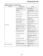
Symptom
Possible cause
Actions
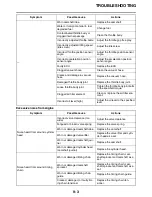
Noise heard from around cylinder
head
Incorrect valve clearance (too
wide)
Adjust the valve clearance.
Fatigued or broken valve spring
Replace the valve spring.
Worn or damaged camshaft lobe
Replace the camshaft.
Worn or damaged valve lifter
Replace the valve lifter and cylin-
der head as a set.
Worn or damaged camshaft jour-
nal
Replace the camshaft.
Worn or damaged cylinder head
(camshaft journal)
Replace the cylinder head.
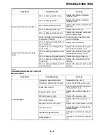
Noise heard from around timing
chain
Worn or damaged timing chain
Replace the timing chain, cam-
shaft sprocket and camshaft as a
set.
Worn or damaged camshaft
sprocket
Replace the timing chain, cam-
shaft sprocket and camshaft as a
set.
Worn or damaged timing chain
guide
Replace the timing chain guide.
Cracked, damaged, or faulty tim-
ing chain tensioner
Replace the timing chain ten-
sioner.
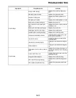
Symptom
Possible cause
Actions
Содержание YZ 2023 Series
Страница 6: ...EAM20162 YAMAHA MOTOR CORPORATION U S A YZ MOTORCYCLE LIMITED WARRANTY...
Страница 10: ......
Страница 44: ...MOTORCYCLE CARE AND STORAGE 1 32...
Страница 61: ...TIGHTENING TORQUES 2 16...
Страница 62: ...CABLE ROUTING DIAGRAM 2 17 EAM20152 CABLE ROUTING DIAGRAM Frame and engine left side view...
Страница 64: ...CABLE ROUTING DIAGRAM 2 19 Frame and engine right side view...
Страница 66: ...CABLE ROUTING DIAGRAM 2 21 Handlebar front view...
Страница 68: ...CABLE ROUTING DIAGRAM 2 23 Frame and engine top view...
Страница 70: ...CABLE ROUTING DIAGRAM 2 25 Frame and battery top view...
Страница 72: ...CABLE ROUTING DIAGRAM 2 27 Rear brake right side view...
Страница 74: ...CABLE ROUTING DIAGRAM 2 29...
Страница 112: ...ELECTRICAL SYSTEM 3 36...
Страница 148: ...REAR BRAKE 4 34 system Refer to BLEEDING THE HYDRAULIC BRAKE SYSTEM on page 3 25...
Страница 154: ...HANDLEBAR 4 40 Throttle grip free play 3 0 6 0 mm 0 12 0 24 in...
Страница 187: ...INSTALLING THE TRANSMISSION 5 74...
Страница 190: ...LUBRICATION SYSTEM CHART AND DIAGRAMS 5 3 1 Oil filter element 2 Oil pump...
Страница 191: ...LUBRICATION SYSTEM CHART AND DIAGRAMS 5 4 1 Intake camshaft 2 Exhaust camshaft...
Страница 192: ...LUBRICATION SYSTEM CHART AND DIAGRAMS 5 5 1 Camshaft 2 Oil pressure check bolt 3 Oil pump 4 Oil filter element...
Страница 245: ...SHIFT SHAFT 5 58 TIP Align the punch mark a on the shift shaft with the punch mark b in the shift pedal 1 1 2 2 a b...
Страница 251: ...OIL PUMP 5 64 A Primary drive gear side B Crankcase cover side 5 7 mm 0 02 0 28 in 5 c d 6 8 b 8 6 7 E...
Страница 264: ...TRANSMISSION 5 77...
Страница 274: ...WATER PUMP 6 9...
Страница 284: ...THROTTLE BODY 7 9...
Страница 286: ...CHECKING THE INTAKE AIR TEMPERATURE SENSOR 8 58 CHECKING THE GEAR POSITION SWITCH 8 58 CHECKING THE INJECTOR 8 59...
Страница 287: ......
Страница 288: ...IGNITION SYSTEM 8 1 EAM20142 IGNITION SYSTEM EAM30277 CIRCUIT DIAGRAM...
Страница 292: ...ELECTRIC STARTING SYSTEM 8 5 EAM20143 ELECTRIC STARTING SYSTEM EAM30279 CIRCUIT DIAGRAM...
Страница 296: ...CHARGING SYSTEM 8 9 EAM20144 CHARGING SYSTEM EAM30282 CIRCUIT DIAGRAM...
Страница 299: ...CHARGING SYSTEM 8 12...
Страница 300: ...SIGNALING SYSTEM 8 13 EAM20154 SIGNALING SYSTEM EAM30348 CIRCUIT DIAGRAM...
Страница 304: ...FUEL INJECTION SYSTEM 8 17 EAM20145 FUEL INJECTION SYSTEM EAM30284 CIRCUIT DIAGRAM...
Страница 329: ...FUEL INJECTION SYSTEM 8 42...
Страница 330: ...FUEL PUMP SYSTEM 8 43 EAM20146 FUEL PUMP SYSTEM EAM30287 CIRCUIT DIAGRAM...
Страница 362: ...SELF DIAGNOSTIC FUNCTION AND DIAGNOSTIC CODE TABLE 9 15...
Страница 372: ...CHASSIS 10 9...
Страница 374: ......
Страница 376: ......
Страница 377: ...YZ250FXP 2023 WIRING DIAGRAM BAJ 2819U 13_WD indd 1 2022 04 01 9 58 37...
Страница 378: ...YZ250FXP 2023 WIRING DIAGRAM BAJ 2819U 13_WD indd 2 2022 04 01 9 58 37...

