MOTORCYCLE CARE AND STORAGE
1-31
stored.
Long-term
Before storing your motorcycle for several
months:
1. Follow all the instructions in the “CARE” on
2. Fill up the fuel tank and add fuel stabilizer (if
available) to prevent the fuel tank from rusting
and the fuel from deteriorating.
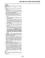
3. Perform the following steps to protect the cyl-
inder, piston rings, etc. from corrosion.
a. Remove the spark plug cap and spark
plug.
b. Pour a teaspoonful of engine oil into the
spark plug bore.
c. Install the spark plug cap onto the spark
plug, and then place the spark plug on the
cylinder head so that the electrodes are
grounded. (This will limit sparking during
the next step.)
d. Turn the engine over several times with
the starter. (This will coat the cylinder wall
with oil.)
e. Remove the spark plug cap from the spark
plug, and then install the spark plug and
the spark plug cap.
WARNING! To pre-
vent damage or injury from sparking,
make sure to ground the spark plug
electrodes while turning the engine
over.
4. Lubricate all control cables and the pivoting
points of all levers and pedals as well as of
the sidestand/centerstand.
5. Check and, if necessary, correct the tire air
pressure, and then lift the motorcycle so that
both of its wheels are off the ground. Alterna-
tively, turn the wheels a little every month in
order to prevent the tires from becoming de-
graded in one spot.
6. Cover the muffler outlet with a plastic bag to
prevent moisture from entering it.
7. Remove the battery and fully charge it. Store
it in a cool, dry place and charge it once a
month. Do not store the battery in an exces-
sively cold or warm place [less than 0
C (32
F) or more than 65
C (149
F)]. For more in-
formation on storing the battery, “CHECKING
AND CHARGING THE BATTERY” on page
8-50.
TIP
Make any necessary repairs before storing the
motorcycle.
Содержание YZ 2023 Series
Страница 6: ...EAM20162 YAMAHA MOTOR CORPORATION U S A YZ MOTORCYCLE LIMITED WARRANTY...
Страница 10: ......
Страница 44: ...MOTORCYCLE CARE AND STORAGE 1 32...
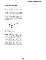
Страница 61: ...TIGHTENING TORQUES 2 16...
Страница 62: ...CABLE ROUTING DIAGRAM 2 17 EAM20152 CABLE ROUTING DIAGRAM Frame and engine left side view...
Страница 64: ...CABLE ROUTING DIAGRAM 2 19 Frame and engine right side view...
Страница 66: ...CABLE ROUTING DIAGRAM 2 21 Handlebar front view...
Страница 68: ...CABLE ROUTING DIAGRAM 2 23 Frame and engine top view...
Страница 70: ...CABLE ROUTING DIAGRAM 2 25 Frame and battery top view...
Страница 72: ...CABLE ROUTING DIAGRAM 2 27 Rear brake right side view...
Страница 74: ...CABLE ROUTING DIAGRAM 2 29...
Страница 112: ...ELECTRICAL SYSTEM 3 36...
Страница 148: ...REAR BRAKE 4 34 system Refer to BLEEDING THE HYDRAULIC BRAKE SYSTEM on page 3 25...
Страница 154: ...HANDLEBAR 4 40 Throttle grip free play 3 0 6 0 mm 0 12 0 24 in...
Страница 187: ...INSTALLING THE TRANSMISSION 5 74...
Страница 190: ...LUBRICATION SYSTEM CHART AND DIAGRAMS 5 3 1 Oil filter element 2 Oil pump...
Страница 191: ...LUBRICATION SYSTEM CHART AND DIAGRAMS 5 4 1 Intake camshaft 2 Exhaust camshaft...
Страница 192: ...LUBRICATION SYSTEM CHART AND DIAGRAMS 5 5 1 Camshaft 2 Oil pressure check bolt 3 Oil pump 4 Oil filter element...
Страница 245: ...SHIFT SHAFT 5 58 TIP Align the punch mark a on the shift shaft with the punch mark b in the shift pedal 1 1 2 2 a b...
Страница 251: ...OIL PUMP 5 64 A Primary drive gear side B Crankcase cover side 5 7 mm 0 02 0 28 in 5 c d 6 8 b 8 6 7 E...
Страница 264: ...TRANSMISSION 5 77...
Страница 274: ...WATER PUMP 6 9...
Страница 284: ...THROTTLE BODY 7 9...
Страница 286: ...CHECKING THE INTAKE AIR TEMPERATURE SENSOR 8 58 CHECKING THE GEAR POSITION SWITCH 8 58 CHECKING THE INJECTOR 8 59...
Страница 287: ......
Страница 288: ...IGNITION SYSTEM 8 1 EAM20142 IGNITION SYSTEM EAM30277 CIRCUIT DIAGRAM...
Страница 292: ...ELECTRIC STARTING SYSTEM 8 5 EAM20143 ELECTRIC STARTING SYSTEM EAM30279 CIRCUIT DIAGRAM...
Страница 296: ...CHARGING SYSTEM 8 9 EAM20144 CHARGING SYSTEM EAM30282 CIRCUIT DIAGRAM...
Страница 299: ...CHARGING SYSTEM 8 12...
Страница 300: ...SIGNALING SYSTEM 8 13 EAM20154 SIGNALING SYSTEM EAM30348 CIRCUIT DIAGRAM...
Страница 304: ...FUEL INJECTION SYSTEM 8 17 EAM20145 FUEL INJECTION SYSTEM EAM30284 CIRCUIT DIAGRAM...
Страница 329: ...FUEL INJECTION SYSTEM 8 42...
Страница 330: ...FUEL PUMP SYSTEM 8 43 EAM20146 FUEL PUMP SYSTEM EAM30287 CIRCUIT DIAGRAM...
Страница 362: ...SELF DIAGNOSTIC FUNCTION AND DIAGNOSTIC CODE TABLE 9 15...
Страница 372: ...CHASSIS 10 9...
Страница 374: ......
Страница 376: ......
Страница 377: ...YZ250FXP 2023 WIRING DIAGRAM BAJ 2819U 13_WD indd 1 2022 04 01 9 58 37...
Страница 378: ...YZ250FXP 2023 WIRING DIAGRAM BAJ 2819U 13_WD indd 2 2022 04 01 9 58 37...

