25
Auch hier ist ein Hochdruckschwimmer-Regler zwischen
Verflüssiger und Abscheider montiert, der das Kondensat
auf den Mitteldruck entspannt. Ein zweiter Regler wird
verwendet, um das Kältemittel zur Niederdruckseite zu
entspannen. Zweistufige Kälteanlagen mit Hochdruck-
schwimmer-Regelung haben einen verbesserten Wir-
kungsgrad und vermeiden hohe Endtemperaturen der
Verdichtung
The system uses a float regulator between condenser
and surge drum, this expands the liquid refrigerant to the
intermediate pressure. A second regulator is used to
expand the liquid refrigerant further to the low-pressure
side of the system.
Two stage refrigeration systems with float regulation
have an improved efficiency and avoid very high gas
temperatures for second stage compression.
Da der zwischen MD- und ND-Seite montierte
Hochdruckschwimmer-Regler das Kältemittel aus
dem MD-Behälter bis zu seinem Abgriffspunkt zur
ND-Seite ableitet, ist der ND-Behälter so auszu-
führen, dass die komplette schwankende Kälte-
mittelmenge aufgenommen werden kann (ND-
Seite und Überschuss der MD-Seite!).
As all the liquid from the condenser and inter-
mediate vessel up to the connection to the
second float regulator is passed to the surge
drum on the low pressure side, this has to be
designed to accommodate the full amount of
fluctuating refrigerant charge (low pressure side
and excess of the intermediate side.
5.1.3 Abtauen von Verdampfergruppen
5.1.3 Hot Gas Defrosting of evaporators
Bei gängigen Abtauzeiten der Verdampfer (ca. 30 min)
reicht für die Auslegung des Hochdruckschwimmer-
Reglers eine 1,5 - 2 fache Leistung der gleichzeitig abtau-
enden Verdampfer aus. Sollten kürzere Abtauzeiten erfor-
derlich sein, muss die Leistung auf das 3 – 4-fache der
gleichzeitig abtauenden Verdampfer erhöht werden.
For common defrost periods (ca. 30 min) the high side
float regulator has to be sized for 1,5 - 2 times the ca-
pacity of the evaporators that are defrosted at the same
time. If shorter defrost periods are required the capacity
has to be increased up to 3 – 4 times the capacity of the
evaporators that are defrosted at the same time.
Die konventionelle Methode Verdampfer abzutauen ist in
nachfolgender Zeichnung 7a beschrieben. Sie bietet sich
an, wenn Verdampfer mit großen Leistungen eingesetzt
werden.
The conventional method of defrosting evaporators is
shown in fig. 7a. This method is used particularly for
evaporators with large capacities.
Dabei wird pro Verdampfer ein Hochdruckschwimmer-
Regler vorgesehen, der das Kondensat in die Saugleitung
zurückführt. Eine Standard-Unterdruckdüse reicht in der
Regel aus, um ein Gaspolster zu verhindern.
There is one high side float regulator for each evaporator
that drains condensate in the common pump return line.
A standard low pressure nozzle is normally sufficient to
avoid a gas buffer in the regulator housing.
Ein hinter dem Regler montiertes Rückschlagventil verhin-
dert ein Rückströmen von Kältemittel, wenn einzelne Ver-
dampfer abgetaut werden.
Diese Funktion kann auch von einem automatisch betätig-
baren Ventil bzw. Kugelhahn übernommen werden.
Wenn der Druck im Normalbetrieb den Öffnungsdruck des
Rückschlagventils übersteigt (z.B. bei Einsatz von Ver-
dampferdruckreglern), sollte auf jeden Fall ein automati-
sches Ventil/Kugelhahn eingesetzt werden.
A check valve that is mounted behind the regulator will
prevent a backflow of refrigerant when other evaporators
are defrosted.
For this function you may also use an automatic oper-
ated valve or ball valve.
If the pressure during the normal refrigeration cycle can
exceed the pressure that will open the check valve (e.g.
when using back pressure regulators) you should always
select an automatic operated valve instead of a check
valve!
Konventionelle Anordnung
Fig. 7a
Conventional defrost installtion
Содержание HR 1 BW
Страница 2: ...2 Montage und Betriebsanleitung HR HS operation and service manual ...
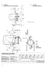
Страница 14: ...14 4 4 Überblick 4 4 Overview Schnittzeichnungen WPHR HR1BW Sectional drawings Fig 2e WP2HR WP3HR Fig 2f HR1BW ...
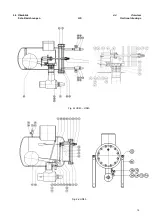
Страница 22: ...22 4 5 GEÄNDERTE VENTILSTELLUNGEN Fig 4a HR 1 3 4 5 MODIFIED VALVE POSITIONS ...
Страница 23: ...23 4 5 geänderte Ventilstellungen Fig 4b HR 4 4 5 Modified Valve Positions ...
Страница 45: ...45 ...


