26
Für die schnelle Kondensatableitung beim Abtauen von
Verdampfergruppen hat sich die nachfolgende, kosten-
günstige Anordnung nach Fig. 7b bewährt.
For fast condensate drainage of evaporators the following
cost-effective arrangement, according to fig. 7b, has worked
well.
Anordnung der Verdampfergruppen
Fig. 7b
Installation of evaporator groups
Bei der Einbindung der Verdampfer ist darauf zu achten,
dass die Heißgasleitung mit etwa 1-2% Gefälle zum HR1
BW verlegt wird (siehe Fig. 7b ).
Der HR1BW leitet das Kondensat der Heißgasleitung ab
und verhindert so ein schlagartiges Verdampfen von Rest-
Flüssigkeit beim Einsetzten der Heißgansabtauung.
When installing the hot gas line use a gradient of app. 1 –
2% to the HR1BW according to fig. 7b.
The HR1BW will drain any condensate that is formed in
the hot gas line so that a sudden evaporation / slug of
liquid is avoided when the hot gas cycle starts.
Am Ende der Kondensatleitung soll ein Hochdruck-
schwimmer-Regler mit verschlossener Unterdruckdüse
montiert werden.
Wenn das Magnetventil nach Beendigung der Heißgasab-
tauung geschlossen wird verhindert das eingeschlossene
Gaspolster, das Flüssigkeit im normalen Betrieb durch den
Regler gedrückt werden kann.
At the end of the condensate drain line there should be a
high-pressure float regulator with closed low-pressure
nozzle
When the solenoid valve closes upon finishing of the hot
gas cycle, the enclosed gas buffer will prevent that any
liquid refrigerant is pushed through the regulator during
normal operation
Ein Überströmventil in einer Bypassleitung zwischen Kon-
densat- und Saugleitung dient der Absicherung der Kon-
densatleitung, falls der Druck unzulässig ansteigt.
Excessive pressure between the liquid condensate and
the pump return line should be avoided by use of a by-
pass line with an overflow valve.
5.1.4 HR1BW zur Ölrückführung
5.1.4 HR1BW for oil return
Alternativ kann der HR 1 BW auch für eine Ölrückführung
eingesetzt werden. Hierzu wird der Regler an der tiefsten
Stelle des Ölabscheiders montiert.
Das sich ansammelnde Öl wird dann automatisch zum
Verdichter zurückgeführt ohne Gas durchzulassen.
Da der HR1BW Öl ständig zum Verdichter zurückführt,
entfällt die Ölvorlage, d.h. es kann weniger Öl eingefüllt
werden!
Alternatively the HR1BW can be used for an oil return.
Therefore the HR1BW should be placed at the lowest
spot of the oil separator.
Any oil that accumulates will automatically be returned to
the compressor without any gas passing through.
Since oil is permanently returned by the HR1BW the oil
charge can be reduced.
Nach Stillstandzeiten kann das Magnetventil in der Ver-
bindung zurück zum Verdichter schon nach wenigen Minu-
ten wieder geöffnet werden, da eventuell im Ölabscheider
kondensiertes Kältemittel sofort im Betrieb verdampft.
After stand-still the solenoid valve in the line between
HR1BW and compressor can be opened only after a few
minutes, because any refrigerant that may have con-
densed will immediately evaporate during operation.
ca. 2%
Содержание HR 1 BW
Страница 2: ...2 Montage und Betriebsanleitung HR HS operation and service manual ...
Страница 14: ...14 4 4 Überblick 4 4 Overview Schnittzeichnungen WPHR HR1BW Sectional drawings Fig 2e WP2HR WP3HR Fig 2f HR1BW ...
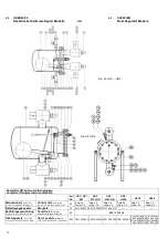
Страница 22: ...22 4 5 GEÄNDERTE VENTILSTELLUNGEN Fig 4a HR 1 3 4 5 MODIFIED VALVE POSITIONS ...
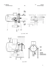
Страница 23: ...23 4 5 geänderte Ventilstellungen Fig 4b HR 4 4 5 Modified Valve Positions ...
Страница 45: ...45 ...


