background image

16 

            Teileliste 


Parts-List


HS 30 

HS 40 

HS 50 

 Spezielle Ersatzteilwünsche nur nach Rücksprache mit dem Lieferanten! 


Teil 


Abmessung 

Artikelnr. 

Abmessung 

Artikelnr. 

Abmessung 

Artikelnr. 


Special parts only upon request


part 


Dimension  

Part - No

.  

Dimension  

Part - No

.  

Dimension  

Part - No

.  


No. 


A

nz

ah

qu

an

tit


A

nz

ah

qu

an

tit


A

nz

ah

qu

an

tit


  Gehäuse 

  main housing 

10 


Typ 3 

----.------ 

Typ 4 

----.------ 

Typ 5 

----.------ 

  Deckel 

  cover plate 

11 


Typ 3 

----.------ 

Typ 4 

----.------ 

Typ 5 

----.------ 

  Eingangsventil 

  outlet valve 

12 


EA 50 

----.------ 

EA 80 

----.------ 

EA 80 

----.------ 

  Entlüftungsventil 

  vent valve 

13 


EE 6 GB/L 

----.------ 

EE 6 GB/L 

----.------ 

EE 6 GB 

----.------ 

  Ablaßventil 

  drain valve 

14 


EA 10 GB/L 

----.------ 

EA 10 GB/L 

----.------ 

EA 10 GB 

----.------ 

  6kt - Schraube 

  cover plate hexagon screw 

21 


M16x60 

12  5111.CLA3BN 

M16x70 

12  5111.CLA3BX 

M16x50 

12  5111.CLA3BD 

  6kt - Schraube 

  hexagon head cap screw 

22a 


---------- 

-- 

----.------ 

---------- 

-- 

----.------ 

M12x35 

5111.CH81AY 

  6kt - Mutter 

  haxagon nut 

22b 


---------- 

-- 

----.------ 

---------- 

-- 

----.------ 

M12 

5151.AH8100 

  Zylinderschraube mit Innen-6kt. 

  hexagon socket screw 

24a 


M8x30 

5112.BC61AT 

M8x45 

2  5112.BC61B8 

---------- 

-- 

----.------ 

  Zylinderschraube mit Innen-6kt. (Sonderkugel)  

  hexagon socket screw 

24b 


M8x45 

5112.BC61B8  

M8x65 

2  5112.BC61BS 

---------- 

-- 

----.------ 

  Zylinderschraube mit Innen-6kt. 

  hexagon socket screw 

25 


M8x20 

5112.BC61AJ 

M8x20 

2  5112.BC61AJ 

M6x20 

5112.BC51AJ 

  Flachdichtung 

  cover plate gasket 

31 


206/225x2 

5632.1FPG8K 

311/330x2 

1  5632.1IMJ5K 

260/280x2 

5632.1H7HRK 

  Dichtung  - Düseneinsatz 

  gasket behind orifice house 

32 


18/50x2 

5632.1AHBDK 

26/50x2 

1  5632.1APBNK 

43/74x2 

5632.1B6C1K 

  Stopfbuchspackung zu 12 

  packing for 12 

33 


12x4 

5642.ABAX02 

19x4 

3  5642.ABBL01 

19x4 

5642.ABBL01 

  Stopfbuchspackung zu 13 + 14 

  packing for 13 + 14 

34 


8/14x8 

5643.ABAP01 

8/14x8 

1  5643.ABAP01 

8/14x8 

5643.ABAP01 

  Stopfbuchspackung zu 50 

  packing for 50 

35 


8/14x8 

5643.ABAP01 

8/14x8 

1  5643.ABAP01 

12x4 

5642.ABAX02 

  Flachdichtung zu 13 + 14 

  gasket for valve cap for 13+14 

36 


10/18x2 

5632.1A9AHK 

10/18x2 

1  5632.1A9AHK 

10/18x2 

5632.1A9AHK 

  Dichtung Düsenhalter 

  gasket at orifice 

37 


45x2 

1-2 

----.------ 

60x2 

1-2 

----.------ 

---------- 

-- 

----.------ 

  Kugel 

  ball 

41 


ø120/ø150 

----.------ 

ø150/ø200 

----.------ 

ø200 

----.------ 

  Kugelarm 

  ball lever 

42 


Typ 2 

----.------ 

Typ 3 

----.------ 

Typ 4 

----.------ 

  Steuerschieber 

  slide valve 

43 


34x15x12.5 

----.------ 

40x25x12.5 

----.------ 

60x40x20.5 

----.------ 

  Düseneinsatz  

  orifice block 

44 


50x35x18 

----.------ 

60x44x26 

----.------ 

75x85x44 

----.------ 

  Bolzen 

  pin 

45 


ø4x25 

----.------ 

ø4x35 

----.------ 

ø4x35x22 

----.------ 

  Scheibe 

  washer 

46 


A 4,3 

----.------ 

A 4,3 

----.------ 

A 4,3 

----.------ 

  Splint 

  solit pin 

47 


ø1x15 

----.------ 

ø1x15 

----.------ 

ø1x15 

----.------ 

  Düsenhalter  

  mount at orifice 

48 


Typ 1 

----.------ 

Typ 2 

----.------ 

Typ 3 

----.------ 

  Aufnahme-Platte  

  mounting plate 

49 


ø60x19 

----.------ 

ø88x25 

----.------ 

---------- 

-- 

----.------ 


  Drehachse 

  stem for hand operation 

50 


ø 8x185 

3591.045010 

ø 8x185 

3591.045010 

ø 14x200 

3591.000125 

  Spannstift zu 50 

  locking pin for 50 

51 


ø 3x10 

5723.AA0301 

ø 3x10 

1  5723.AA0301 

---------- 

-- 

----.------ 


  Exzenter 

  excenter for hand operation 

53 


76-5/10 

3591.043008 

76-5/10 

3591.043008 

ø 40x16 

3591.000117 

  Spannstift zu 53 

  locking pin for 53 

54 


---------- 

-- 

----.------ 

---------- 

-- 

----.------ 

ø 3x30 

5723.AA0302 

  Flachkopfschraube / Bolzen ( HR 4 ) 

  pan head screw/bolt 

55 


M4x5 

5117.AB30A4 

M4x5 

1  5117.AB30A4 

ø 4x25x22 

5724.A00401 

  Zugstange / Druckstab 

  tow/pressure bar 

56 


ø 3x__ 

----.------ 

ø 3x__ 

----.------ 

ø 8x1x235 

3591.000100 

  Zugstange / Druckstab - HR SK 

  tow/pressure bar 

56 


ø 3x__ 

----.------ 

ø 3x__ 

----.------ 

ø 8x1x235 

3591.000100 


  Führungsbügel 

  guide bracket 

57 


67.5x50x15 

----.------ 

65.5x60x15 

----.------ 

---------- 

----.------ 

  Unterdruckförderer 

  low pressure nozzle 

58 


ø 6x1x136 

----.------ 

ø 6x1x230 

----.------ 

ø 6x1x360 

----.------ 

  Hebelstütze  

  column  

60 


HS 3 

3591.042005 

HS 4 

3591.042006 

---------- 

----.------ 

  Kupplungsstück 

  clutch .... 

61a 


ø 14 

2441.001001 

ø 14 

2441.001001 

---------- 

-- 

----.------ 

  Kupplungsstück  

  clutch ....  

61b 


ø 8 

2441.001002 

ø 8 

2441.001002 

---------- 

-- 

----.------ 


  Spannstift/Gewindestift HS 50 

  locking pin/grub screw for HS 50 

63 


---------- 

-- 

----.------ 

---------- 

-- 

----.------ 

M 6x12 

5121.CD50AB 

  Schutzkappe zu 12 

  spindle cap for 12 

71 


SW 27 

6436.AAP270 

SW 46 

1  6436.AAP460 

SW 46 

6436.AAP460 

  Schutzkappe zu 13 + 14 + 50 

  spindle cap for 13+14 + 50 

72 


SW 27 

6436.AAP270 

SW 27 

3  6436.AAP270 

SW 27 

6436.AAP270 

  Stopfbuchse zu 12 

  gland for 12 

73 


SW 17 

6438.000002 

SW 17 

6438.000002 

SW 22 

6438.000003 

  Stopfbuchse zu 50 

  gland for 50 

74 


SW 12 

6438.000001 

SW 12 

6438.000001 

SW 17 

6438.000002 

  Blindkappe 

  blind cap 

75 


G 1/2" 

6436.ABDD00 

G 1/2" 

2  6436.ABDD00 

G 1/2" 

6436.ABDD00 


  Rahmenfuß 

  frame, galvanized 

81 


---------- 

-- 

----.------ 

---------- 

-- 

----.------ 

600x495 

----.------ 

  Entlüftungsbehälter 

  vent container 

91 


---------- 

----.------ 

---------- 

----.------ 

---------- 

----.------ 

  Schlauch komplett 

  hose 

92 


---------- 

----.------ 

---------- 

----.------ 

---------- 

----.------ 

  Schaftschraube 

  threaded pin 

93 


M 10 

----.------ 

M 10 

----.------ 

M 10 

----.------ 

Содержание HR 1 BW

Страница 1: ...Hochdruckschwimmer Regler Montage und Betriebsanleitung High side float regulator Installation and operating instructions HR HS ...

Страница 2: ...2 Montage und Betriebsanleitung HR HS operation and service manual ...

Страница 3: ...MMELBEHÄLTER 43 12 7 EINSATZ VON ÖLKÜHLERN 43 1 INTRODUCION 4 1 1 INTENDED USE 4 1 2 SAFETY REQUIREMENTS 4 1 3 MANUFACTURER DISCLAIMER 4 2 TERMS OF WARRENTY 5 3 TECHNICAL INFORMATION 5 3 1 DESCRIPTION OF TYPES 5 3 2 SCOPE OF DELIVERY 6 3 3 INSPECTIONS CERTIFICATES 7 3 4 ORDERINFORMATION 8 3 5 CONTROL UNIT 9 4 TECHNICAL DATA 11 4 1 MATERIALS 11 4 2 PRESSURE TEMPERATURE RANGE 11 4 3 OVERVIEW 12 4 4 ...

Страница 4: ... Druckangaben dürfen auf keinen Fall überschritten werden Under no circumstances are the stated design temperature and pressure limitations on the data plate to be exceeded Wenn am Eintritts und am Austrittsstutzen Absperr ventile vorgesehen sind so muss sichergestellt wer den dass die Ventile im Betrieb immer voll geöffnet bleiben When installing inlet and outlet valves please ensure that the val...

Страница 5: ... regarding timing and execution Parts that are used during maintenance or service are not the approved genuine TH WITT spare parts 3 TECHNISCHE INFORMATION 3 TECHNICAL INFORMATION 3 1 TYPENBEZEICHNUNG 3 1 DESCRIPTION OF TYPES Es sind vier Baugrößen der Standard Hochdruckschwimmer HR1 bis HR4 lieferbar Außerdem bieten wir modular aufge baute Regler vom Typ HS30 bis HS50 WPHR Schwimmer für Wärmepump...

Страница 6: ...sergefäß mit Schlauchverbindung zum Entlüftungsventil Einzelabnahme durch TÜV andere Prüfgesellschaften Sonderausführungen auf Anfrage OPTIONAL SCOPE OF DELIVERY HR Support brackets or mounting frame supplied loose Alternative valve connection positions see chapter 4 5 Closed low pressure nozzle Gas purge kit special water container with hose and connection to the purge valve Individual inspection...

Страница 7: ...IN Eintrittsstuten Absperrventil EA10 am Austritt Blindkappe am Hebelaustritt STANDARD SCOPE OF DELIVERY HR1BW DIN inlet connection Stop valve EA10 at the outlet Cap for hand lever control 3 3 ABNAHMEN BESCHEINIGUNGEN 3 3 INSPECTIONS CERTIFICATES Hochdruckschwimmer Regler werden als druckhaltende Ausrüstungsteile ausgelegt gefertigt und mit einer CE Kennzeichnung gemäß Druckgeräterichtlinie ausgel...

Страница 8: ...dard requirements Bestelltext z B HR3 H mit N Kugel oder bei HS Reglern steht die erste Zahl für die Baugröße und die zweite Zahl bedeutet 1 N Kugel ohne Unterdruckdüse 2 spezielle SK Kugel ohne Unterdruckdüse 3 R Kugel ohne Unterdruckdüse 4 N Kugel mit Unterdruckdüse 5 spezielle SK Kugel mit Unterdruckdüse 6 R Kugel mit Unterdruckdüse z B HS34 M HS Regler mit N Kugel mit Unterdruckdüse und in M A...

Страница 9: ... HR4 H N N N 333 236 154 6 0 6 0 4 0 200 200 200 300 300 300 2 65 2 65 2 65 3591 000262 HR4 SK H 146 4 0 230 300 2 5 3591 000259 3591 000260 3591 000261 HR4 L HR4 M HR4 H R R R 470 333 236 6 0 6 0 4 0 150 150 150 300 300 300 3 36 3 36 3 36 Steuereinheiten komplett bis 05 2009 Control unit complete until 05 2009 Artikel Nr Article No Typ Model Kugel Art Ball type Drossel Orifice Unterdruckdüse ø Lo...

Страница 10: ...hne without 120 120 95 87 0 65 0 65 3591 713029 3591 713030 3591 713031 HS34 L HS34 M HS34 H N N N 56 37 19 mit with 120 120 120 95 87 87 0 44 0 44 0 44 3591 713032 3591 713033 3591 713034 HS35 L HS35 M HS35 H SK SK SK 52 30 19 mit with 150 150 150 87 87 87 0 70 0 70 0 70 3591 713035 3591 713036 HS36 M HS36 H R R 56 37 mit with 120 120 95 87 0 65 0 65 3591 813021 3591 813022 3591 813023 HS41 L HS4...

Страница 11: ...9 2 W9 1 W9 2 2k Epoxydharz nach DIN ISO 12944 5 RAL 7001 Housing P 265 GH St 35 8 Flange P 265 GH End caps P 265 GH Bolts A2 70 Gaskets Centellen Cap Al Gland Al Packing Ne Lever St Painting system W9 1 W9 2 W9 1 W9 2 2 k epoxy finish according to DIN ISO 12944 5 RAL 7001 4 2 DRUCK TEMPERATUR BEREICHE 4 2 PRESSURE TEMPERATURE RANGE HR HS50 und HR1BW Hochdruckschwimmer Regler Max zul Druck PS 25 b...

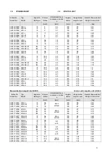
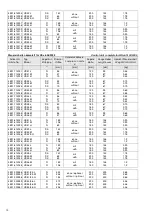
Страница 12: ...4 Kap 3 4 chap 3 4 Kap 3 4 chap 3 4 Kap 3 4 chap 3 4 Kap 3 4 chap 3 4 Befestigungskonsole Brackets 70 3911 000010 3911 000010 3911 000010 Entlüftungsvorrichtung Nur für NH3 mit Teilen 91 92 93 Vent Device Only for ammonia with parts 91 92 93 90 3591 000346 bis until 05 2009 3591 000395 bis until 05 2009 3591 000396 Dichtungssatz mit Teilen 1x31 1x32 6x33 2x34 1x35 2x36 Set of gaskets with parts 1x...

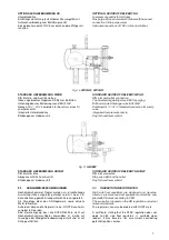
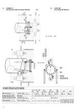
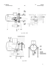
Страница 13: ...13 4 4 Überblick 4 4 Overview Schnittzeichnungen HS Sectional drawings Fig 2c HS30 HS40 Fig 2d HS50 Fig 2c HS30 HS40 ...

Страница 14: ...14 4 4 Überblick 4 4 Overview Schnittzeichnungen WPHR HR1BW Sectional drawings Fig 2e WP2HR WP3HR Fig 2f HR1BW ...

Страница 15: ... 3 6 A 4 3 6 A 4 3 6 A 4 3 6 Splint solit pin 47 ø 1x15 2 ø 1x15 2 ø 1x15 2 ø 1x15 2 Düsenhalter WP 2 3 HR mount at orifice 48 Typ 1 1 Typ 2 1 Aufnahme Platte WP 2 3 HR mounting plate 49 ø 45x19 1 ø 60x19 1 Drehachse spindle 50 ø 8x115 1 3591 000123 ø 8x135 1 3591 000124 ø 8x135 1 3591 000124 ø 14x200 1 3591 000125 Drehachse für WP 65bar Spindle for WP 65bar 50 ø 8x200 1 3591 000120 Spannstift zu ...

Страница 16: ...arm ball lever 42 Typ 2 1 Typ 3 1 Typ 4 1 Steuerschieber slide valve 43 34x15x12 5 1 40x25x12 5 1 60x40x20 5 1 Düseneinsatz orifice block 44 50x35x18 1 60x44x26 1 75x85x44 1 Bolzen pin 45 ø4x25 2 ø4x35 2 ø4x35x22 2 Scheibe washer 46 A 4 3 6 A 4 3 6 A 4 3 6 Splint solit pin 47 ø1x15 2 ø1x15 2 ø1x15 2 Düsenhalter mount at orifice 48 Typ 1 1 Typ 2 1 Typ 3 1 Aufnahme Platte mounting plate 49 ø60x19 1 ...

Страница 17: ...x2 9 13 HR2 50 71 5 105 160 250 194 480 445 285 200 90 450 42 4x2 6 42 4x3 6 23 HR3 90 95 115 160 345 273 640 555 395 260 135 530 60 3x2 9 60 3x4 0 54 a1 inch a2 inch e1 inch e2 inch d1 inch d2 inch l1 inch l2 inch l3 inch h1 inch h2 inch h inch d x s inch d x s1 inch Gewicht Weight lb HR1 1 81 2 09 3 54 6 3 7 87 5 47 17 32 16 73 10 43 7 87 2 56 15 35 1 06x0 09 1 06x0 11 28 6 HR2 1 97 2 81 4 13 6 ...

Страница 18: ... 4 4 Abmessungen Fig 3b 4 4 Dimensions HR 4 HR4 mit Absperrventilen am Eintritt und Austritt HR4 with stop valves at inlet and outlet HR4 mit Schedule 40 Anschluss stutzen HR4 with Schedule 40 connections ...

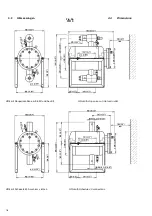
Страница 19: ...t Weight kg HS30 90 255 180 290 219 1 114 3x3 6 60 3x2 9 115 555 510 655 460 155 127 49 HS40 147 355 262 400 323 9 168 3x4 5 88 9x5 6 155 750 685 775 585 194 154 107 a1 inch a2 inch a3 inch d1 inch d2 inch d3xs1 inch d4xs2 inch e1 inch h inch h1 inch l1 inch l2 inch l3 inch l4 inch Gewicht Weight lb HS30 3 7 10 04 7 08 11 42 8 63 4 5x0 24 2 37x0 16 4 53 21 8 20 08 25 79 18 11 6 10 5 00 108 02 HS40...

Страница 20: ...20 4 4 Abmessungen Fig 3d 4 4 Dimensions HS 50 HS50 mit Austrittsventil HS50 with stop valve at the outlet HS50 mit Schedule 40 Anschluss Stutzen HS50 with Schedule 40 connections ...

Страница 21: ...75 275 345 273 640 545 60 3x2 9 61 WP3HR 65bar 270 150 375 275 355 273 650 545 60 3x2 9 68 a1 inch a2 inch b inch e inch d1 inch d2 inch l1 inch h inch dxs inchxinch Gewicht Weight lb WP2HR 7 87 3 94 10 83 9 06 9 84 7 64 18 7 18 11 1 67x0 1 57 32 WP3HR 10 63 5 51 14 76 10 83 13 58 10 75 25 2 21 46 2 37x0 11 134 48 WP3HR 65bar 10 63 5 90 14 76 10 83 13 98 10 75 25 6 21 46 2 37x0 11 150 00 Fig 3f HR...

Страница 22: ...22 4 5 GEÄNDERTE VENTILSTELLUNGEN Fig 4a HR 1 3 4 5 MODIFIED VALVE POSITIONS ...

Страница 23: ...23 4 5 geänderte Ventilstellungen Fig 4b HR 4 4 5 Modified Valve Positions ...

Страница 24: ...druck schwimmer Reglers befindet sich hinter dem Hoch druckschwimmer Regler ein Flüssigkeits Gasgemisch das zum Abscheider strömt Vom Abscheider aus kann das Gas wieder dem Verdich ter bzw die Flüssigkeit den Verdampfern zugeführt werden Die Kondensattemperatur kann sich den äußeren Gege benheiten entsprechend optimal anpassen wodurch eine sehr energiesparende Betriebsweise gewährleistet wird Eine...

Страница 25: ...defrost periods ca 30 min the high side float regulator has to be sized for 1 5 2 times the ca pacity of the evaporators that are defrosted at the same time If shorter defrost periods are required the capacity has to be increased up to 3 4 times the capacity of the evaporators that are defrosted at the same time Die konventionelle Methode Verdampfer abzutauen ist in nachfolgender Zeichnung 7a besc...

Страница 26: ... enclosed gas buffer will prevent that any liquid refrigerant is pushed through the regulator during normal operation Ein Überströmventil in einer Bypassleitung zwischen Kon densat und Saugleitung dient der Absicherung der Kon densatleitung falls der Druck unzulässig ansteigt Excessive pressure between the liquid condensate and the pump return line should be avoided by use of a by pass line with a...

Страница 27: ...ce area Wenn der Flüssigkeitsstand im Schwimmer fällt wird der Schieber über die Öffnung bewegt und verschließt so den Auslaß Wenn die Schwimmerkugel unten angelangt sorgen die geläppten Oberflächen von Schieber und Auslaß für einen dichten Abschluss Der Auftrieb des Schwimmkörpers ist ab hängig von Durchmesser und Gewicht der Kugel und von der Dichte der abzuleitenden Flüssigkeit As the liquid le...

Страница 28: ...ermittelte Leistungsverlust im Bereich unterhalb 1 der Nennleistung verbleibt Factory selection of the low pressure nozzle is made in such a way that the theoretically calculated loss of ca pacity due to gas by pass is less than 1 of the nominal capacity 5 3 1 Anlagen mit verschlossener Unterdruckdüse 5 3 1 Plant with closed low pressure nozzle Bei HR Reglern kann die vorhandene Unterdruckdüse bei...

Страница 29: ... großzügig bemessen sein gleiche Dimension wie der Anschluß am Reglergehäuse Außerdem sollte die Leitung so kurz wie möglich auf direktem Weg und ohne Widerstände verlegt werden Zusätzliche Bögen Reduzierungen oder Armaturen sollten vermieden werden Eine Gasblase soll unge hindert zum Verflüssiger aufsteigen können When using HS regulatos without low pressure nozzle it should be sonsidered that th...

Страница 30: ...egulating effort Im Gegensatz zur Niederdruckschwimmer Regelung befin det sich die schwankende Kältemittelmenge im Zentralab scheider In contrast to low pressure regulators the entire fluctuat ing refrigerant charge is located in the central surge drum 6 2 AUSWAHLKRITERIEN 6 2 SELECTION CRITERIA Für die Auslegung von WITT Hochdruckschwimmer Regler verweisen wir auf unser Auslegungsprogramm dass Si...

Страница 31: ...ith a common collector has to be selected special care must be taken that only equally sized models of condensers are installed in parallel and that they are arranged symmetrically This is to ensure the pressure drop in the condensers and in the lines to the common liquid receiver are approxi mately the same When different condenser types are installed or an asym metric arrangement is made the dif...

Страница 32: ...allelschaltung sollten die Regler gemäß nach folgender Abbildung übereinander angeordnet werden Um den Leistungsverlust durch mehrere Unterdruckdüsen zu vermeiden ist es empfehlenswert die Unterdruckdüse des oberen Reglers zu verschließen und deren Funktion durch ein Magnetventil zu ersetzen For parallel arrangement install the regulators according to the schematic below To avoid a loss of efficie...

Страница 33: ... wie Filter oder Trockner dürfen auf kei nen Fall vorgesehen werden Internal filters or dryers are not permitted in the liquid feed line 6 4 2 Anschluss an Hochdruckbehälter 6 4 2 Connection to a HP receiver Wenn die Zulaufleitung an einen Druckbehälter angeschlos sen werden soll z B einen Sammler einen Vorlagebehälter oder an einen Zwischenkühler so ist gemäß nachfolgender Darstellung Fig 14a zu ...

Страница 34: ...erflüssigers häufig schwankt ist auf einen ausreichend dimensionierten Siphon zu achten As the internal pressure difference within the plate chan nels fluctuates a sufficiently laid out siphon duck neck drain connection has to be used Gestaltung des Siphons bei Anschluss an einen Plattenapparat Fig 15 Schematic of the siphon connecting to a plate condenser 6 5 EINSPRITZLEITUNG 6 5 LOW PRESSURE LIN...

Страница 35: ...or debris 8 MONTAGE 8 INSTALLATION Montagearbeiten an den Hochdruckschwimmer Reglern sind grundsätzlich nur von sachkundigem Personal durchzuführen Any work on float regulators must be carried out by trained and knowledgeable personnel experi enced in installation and service of refrigeration systems 8 1 MONTAGEVORBEREITUNG 8 1 PREPARING FOR INSTALLATION Vor Montage des Hochdruckschwimmer Reglers ...

Страница 36: ...Nocken für Sicherheitsventile vorgesehen All HR regulators above size HR 2 the housing is equipped with a safety valve connection Drehen Sie den Hebel für die Schwimmerarretierung nach Abschluss der Montagearbeiten nach unten Das Loch im Hebel müssen nach unten zeigen für Automatikbetrieb When the installation is complete turn the lever downwards to unlock the transportation securing device of the...

Страница 37: ...el vollstän dig abgesaugt sein bevor die Verschraubungen ge löst werden When the high pressure float regulator HR is to be maintained the housing must be completely de pressurised and all the refrigerant entirely removed before loosening any screws and opening up Beim Öffnen der Regler kann es zu einer plötzlichen Verdampfung von eingeschlossenem Kältemittel kommen Deshalb unbedingt Schutzkleidung...

Страница 38: ...e hierzu auch Fig 16a und 16b HR1 HR3 refer to Fig 16a and 16b Entfernen Sie bei den Typen HR1 bis HR 3 das Ge häuse Drehen Sie die Schraube M 4 x 5 Pos 55 heraus Schrauben Sie Zylinderschrauben M 8 x 20 Pos 25 aus dem Gehäusedeckel heraus Entfernen Sie Führungsbügel Pos 57 und Zugstan ge Pos 56 Tauschen Sie die komplette Steuereinheit aus Ersetzen Sie Flachdichtung Pos 32 Montieren Sie Führungsbü...

Страница 39: ...the cover gasket during re assemby Proceed per chapter 9 Fig 16 c Fig 16 d HS30 HS40 WPHR siehe Fig 2c 2e sowie 16 c 16 d HS30 HS40 WPHR see fig 2c 2e and fig 16c 16d Entfernen Sie den Deckelflansch Pos 11 indem Sie die Schrauben Pos 21 entfernen Dabei wird der Hebel für die Funktionskontrolle aus der Kupplung gelöst Durch Entfernen der Zylinderschrauben Pos 25 kann die komplette Steuereinheit ent...

Страница 40: ...muss oder das Eindringen von Luft nicht vermieden werden kann z B wenn Gleitringdichtungen von Verdichtern im Vacuum laufen ist eine automatische Entlüftungseinrichtung sehr zu empfehlen When purging is necessary regularly or air intake cannot be excluded e g shaft seals of compressors are operating in vacuum an automatic purger is highly recommended Das nachfolgend Fig 17 dargestellte WITT Zubehö...

Страница 41: ...orifice is increased Das Gehäuse wie zuvor beschrieben entleeren und drucklos machen bevor die Schrauben gelöst warden Nach Abnahme des Deckels Gehäuses kann die Funktion des Reglers gut beobachtet und geprüft werden The housing should be drained and purged as described before before any srews are loosened Upon taking the cover housing off the function of the regulator can be observed and checked ...

Страница 42: ...dung in der Leitung zum Hochdruckschwimmer Regler führt With parallel installation of condensers in a common feed line to the float regulator it has often be observed that the different line pressure drops causes flash gas formation in the feed line to the high pressure float regulator Die Temperaturen am Austritt der einzelnen Verflüssiger sind zu überprüfen Wenn eine Unterkühlung des Konden sats...

Страница 43: ...ust ensure that there is always sufficient liquid refrigerant in the HP receiver The high pressure receiver should be sufficiently sized so that the oil cooler can be supplied with refrigerant for at least 5 min before refrigerant is returned from the condensers Caution Be aware under certain start up conditions of the system the surge drum can rapidly empty of refriger ant Beim Einbinden des Regl...

Страница 44: ...u klein dimensionierter Verflüssiger zu große Kälteleistung im Anfahrzustand Condensing pressure is too high without back up Condenser does not transfer any heat Too small condenser Capacity is too large during start up 4 Zu hoher Verflüssi gungsdruck durch Rückstau Luft in der Anlage siehe Kap 12 1 Dampfbildung in der Zulaufleitung siehe Kap 12 2 Verflüssiger parallel angeordnet siehe Kap 12 3 Ei...

Страница 45: ...45 ...

Страница 46: ...TH WITT Kältemaschinenfabrik GmbH Lukasstraße 32 52070 Aachen Germany Tel 49 0 241 18208 0 Fax 49 0 241 18208 49 info th witt com W 3510 6 01c 4 0702 www th witt com ...

Отзывы: