6
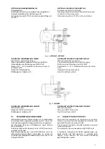
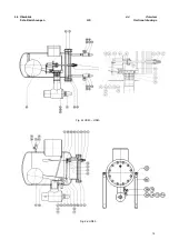
Fig.1a
HR 1 – 3
Fig. 1b
HR 4
3.2
LIEFERUMFANG
3.2
SCOPE OF DELIVERY
STANDARD LIEFERUMFANG HR
Absperrventile am Eintritt- und Austrittsstutzen bzw.
ASTM-Stutzen Schedule40 (bitte angeben)
Oben angebrachtes Regelventil zum Entlüften (EE3 bzw.
EE6 bei HR4)
Unten angebautes Entleerungsventil EA10 GB
Nocken G ½” / G ¼” kombiniert für Anschluss eines Si-
cherheitsventils (ab HR2)
Integrierte Unterdruckdüse
Blindkappe am Hebelaustritt
Rahmen, nur für den HR4
STANDARD SCOPE OF DELIVERY HR
Stop valves at inlet and outlet respective ASTM connec-
tions schedule 40 (please specify)
Top mounted regulating valve for purging (EE3 resp.
EE6 for HR4)
Bottom mounted drainage valve EA10GB
Combined G ½” / G ¼” threaded connection for safety
valve (larger than HR2)
Integrated low pressure nozzle
Cap for hand lever control
mounting frame, only for HR4
OPTIONALER LIEFERUMFANG HR
Befestigungskonsolen (lose beigepackt)
abweichende Ventilstellung (siehe Kap. 4.5)
Unterdruckdüse verschlossen
Entlüftungseinrichtung (aufsetzbares Wassergefäß mit
Schlauchverbindung zum Entlüftungsventil)
Einzelabnahme durch TÜV / andere Prüfgesellschaften
Sonderausführungen auf Anfrage
OPTIONAL SCOPE OF DELIVERY HR
Support brackets or mounting frame (supplied loose)
Alternative valve connection positions (see chapter 4.5)
Closed low pressure nozzle
Gas purge kit (special water container with hose and
connection to the purge valve)
Individual inspections of TÜV or other institutions
Special non standard executions upon request
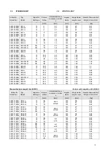
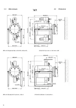
Fig 1c
HS30 – HS40
Fig. 1d
HS50
STANDARD LIEFERUMFANG HS
DIN- oder ASTM (Schedule 40) Eintrittsstutzen (bitte an-
geben)
Absperrventil oder ASTM-Stutzen am Austritt (bitte unbe-
dingt angeben)
Verlängertes Einstellventil EE6 zum Entlüften, oben am
Deckel montiert
Verlängertes Absperrventil EA10GB zum Entleeren, unten
am Deckel montiert
Blindkappe am Hebelaustritt
Rahmen, nur für HS50
STANDARD SCOPE OF DELIVERY HS
DIN-or ASTM (Schedule 40) inlet connection (please
specify)
Stop valve or ASTM connection at the outlet (please
specify)
Extended purge valve EE6, top mounted in the cover
plate
Extended stop valve EA10 GB for drainage, bottom
mounted in the cover plate
Cap for hand lever control
Mounting frame, only for HS50
Содержание HR 1 BW
Страница 2: ...2 Montage und Betriebsanleitung HR HS operation and service manual ...
Страница 14: ...14 4 4 Überblick 4 4 Overview Schnittzeichnungen WPHR HR1BW Sectional drawings Fig 2e WP2HR WP3HR Fig 2f HR1BW ...
Страница 22: ...22 4 5 GEÄNDERTE VENTILSTELLUNGEN Fig 4a HR 1 3 4 5 MODIFIED VALVE POSITIONS ...
Страница 23: ...23 4 5 geänderte Ventilstellungen Fig 4b HR 4 4 5 Modified Valve Positions ...
Страница 45: ...45 ...


