19
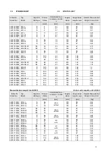
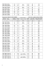
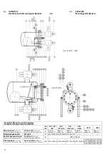
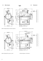
4.4 Abmessungen
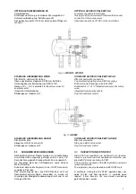
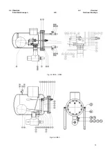
Fig. 3c
4.4 Dimensions
HS 30 -40
HS30 /HS40 mit Austrittsventil
HS30 /HS40 with outlet stop-valve
HS30 /HS40 mit Schedule 40 Anschlüssen
HS30 /HS40 with Schedule 40 connections
a1
mm
a2
mm
a3
mm
d1
mm
d2
mm
d3xs
mmxmm
d4xs
mmxmm
e1
mm
h
mm
h1
mm
l1
mm
l2
mm
l3
mm
l4
mm
Gewicht
Weight
kg
HS30
90
255
180
290
219,1 114,3x3,6 60,3x2,9
115
555
510
655
460
155
127
49
HS40
147
355
262
400
323,9 168,3x4,5 88,9x5,6
155
750
685
775
585
194
154
107
a1
inch
a2
inch
a3
inch
d1
inch
d2
inch
d3xs1
inch
d4xs2
inch
e1
inch
h
inch
h1
inch
l1
inch
l2
inch
l3
inch
l4
inch
Gewicht
Weight
lb
HS30
3.7 10.04 7,08 11.42 8.63
4.5x0.24 2.37x0.16 4.53
21.8 20.08 25.79 18.11 6.10
5,00
108,02
HS40
5.79
14
10,31 15.75 12.75 6.63x0.28 2.71x0.22
6.1
29.52 26.97 30.51 23.03 7.68
6.06
235,89
Содержание HR 1 BW
Страница 2: ...2 Montage und Betriebsanleitung HR HS operation and service manual ...
Страница 14: ...14 4 4 Überblick 4 4 Overview Schnittzeichnungen WPHR HR1BW Sectional drawings Fig 2e WP2HR WP3HR Fig 2f HR1BW ...
Страница 22: ...22 4 5 GEÄNDERTE VENTILSTELLUNGEN Fig 4a HR 1 3 4 5 MODIFIED VALVE POSITIONS ...
Страница 23: ...23 4 5 geänderte Ventilstellungen Fig 4b HR 4 4 5 Modified Valve Positions ...
Страница 45: ...45 ...


