27
5.1.5 Selbstheilungseffekt
5.1.5 Recovery Effect
Auf HD-seitige Sammler sollte grundsätzlich verzichtet wer-
den:
The installation of a HP-receiver must generally be
avoided.
Bei zu klein ausgelegtem Regler tritt ein Rückstau des Kälte-
mittels ein. Dieser Rückstau bewirkt, dass sich die wirksame
Verflüssigerfläche verkleinert und der Kondensationsdruck
solange ansteigt, bis der Regler in der Lage ist, das anfallen-
de Kondensat abzuführen. Mit zwischengeschalteten Samm-
lern kann diese günstige Eigenschaft nicht genutzt werden, da
zunächst der Sammler gefüllt wird, bevor sich Kältemittel im
Kondensator zurückstauen kann!
Achtung: Durch die Verlagerung des Kältemittels zur HD-Seite
(erkennbar an einer messbaren Unterkühlung des Konden-
sats) kann der Minimalstandsalarm auf der ND-Seite ausge-
löst werden.
When the float regulator is selected too small, refriger-
ant will back-up into the condenser. This back up has
the result that the effective condenser surface will be
decreased and the condensing pressure will raise until
the float regulator is again capable to release the accu-
mulated condensate. With a high-pressure receiver
installed in between the two components this very help-
ful characteristic cannot be used, since the receiver will
be filled first before any condensate will build up in the
condenser.
Caution: If too much liquid migrates to the high-pressure
side (this can be checked by sensing the sub cooling of
condensate) the llow-evel alarm of the LP surge drum
may be activated.
Wird die maximal zulässige Druckdifferenz überschrit-
ten, z.B. bei hohen Kondensationstemperaturen, kann
der Auslassmechanismus des Reglers blockiert wer-
den!
If the maximum allowable differential pressure is
exceeded, e.g. at high condensate temperatures,
the outlet mechanism of the regulator may be-
come blocked!
5.2
SCHWIMMER-REGELUNG
5.2
FLOAT REGULATION
Das in das Hochdruckschwimmer-Regler Gehäuse eintreten-
de Kondensat bewirkt dort, dass der Schwimmkörper angeho-
ben wird. Über eine Hebelübersetzung wird ein Schieber betä-
tigt, der einen entsprechenden Anteil der Drosselöffnung frei-
gibt und das Kondensat zum Abscheider ablässt.
Weil der Schwimmkörper Reibungskräfte überwinden muss,
findet ein schrittweises Verstellen der Öffnung statt.
Liquid condensate flows into the regulator housing lifting
the float ball. This movement is transmitted to the moving
part of a slide valve block, which in turn proportionally
exposes the mating seat orifice releasing condensate to
the surge drum.
Since the float has to overcome friction, there is a pro-
gressive exposure of the orifice area.
.
Wenn der Flüssigkeitsstand im Schwimmer fällt wird der
Schieber über die Öffnung bewegt und verschließt so den
Auslaß. Wenn die Schwimmerkugel unten angelangt sorgen
die geläppten Oberflächen von Schieber und Auslaß für einen
dichten Abschluss. Der Auftrieb des Schwimmkörpers ist ab-
hängig von Durchmesser und Gewicht der Kugel und von der
Dichte der abzuleitenden Flüssigkeit.
As the liquid level drops, the slide block moves back over
the orifice closing the outlet.
When the float ball is down at its lowest position the pre-
cisely machined surfaces of slide block and orifice area
will seal tightly. Movement of the float depends on the
diameter and weight of the ball as well as the density of
the liquid refrigerant
Für Kältemittel mit geringer Dichte sind die SK-Kugeln bei den
HS Reglern vorgesehen.
For refrigerants with low density we have alternative SK-
balls to be integrated in the HS type regulators.
Beim WP HR sind die Schwimmerkugeln unten offen. Durch
Gasansammlung innerhalb der Kugel schwimmt diese auf und
gibt die Drosselöffnung frei. Aus diesem Grund dürfen die
Hochdruckschwimmer-Regler WP HR
nicht unterhalb des
Verflüssigers angeordnet werden.
With the WP HR the ball float is open at the bottom. Due
to gas formation within the ball it will move upwards, ex-
posing a part of the orifice area. This is why high-
pressure float regulator WP HR
are not to be mounted
underneath the condenser.
5.3
FUNKTION DER UNTERDRUCKDÜSE
5.3
FUNCTION OF THE LOW PRESSURE NOZZLE
Damit anfallendes Kondensat selbstständig dem Regler zu-
fließen kann, wäre es eigentlich erforderlich den Regler unter-
halb des Verflüssigers anzuordnen. Um eine Anordnung auch
oberhalb des Verflüssigers zu ermöglichen, sind mit Ausnah-
me des HR1BW, alle HR und WPHR Hochdruckschwimmer-
Regler mit einer internen Unterdruckdüse ausgestattet. Bei
HS-Reglern ist die Unterdrückdüse optional erhältlich.
To enable any liquid condensate to flow to the regulator
by gravity, it would be necessary to arrange the regulator
underneath the condenser.
To permit an installation with the regulator above the
condenser, all HR and WP HR float regulators, with the
exception of the HR1BW, are equipped with an internal
low-pressure. HS-regulators may also be ordered with
low-pressure nozzle (optional).
Die Unterdruckdüse verbindet den Gasraum des Gehäuses
mit dem Austrittsstutzen. Aufgrund der Druckdifferenz zwi-
schen Hochdruck- und Niederdruckseite wird Gas aus dem
Gehäuse zur Niederdruckseite angesaugt und im Gehäuse
entsteht ein leichter Unterdruck.
This low pressure nozzle connects the gas space in the
housing with the outlet connection. Due to the pressure
difference between high and low pressure side, the gas
is drawn to the low-pressure side resulting in a slight
under pressure in the housing.
Содержание HR 1 BW
Страница 2: ...2 Montage und Betriebsanleitung HR HS operation and service manual ...
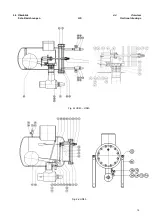
Страница 14: ...14 4 4 Überblick 4 4 Overview Schnittzeichnungen WPHR HR1BW Sectional drawings Fig 2e WP2HR WP3HR Fig 2f HR1BW ...
Страница 22: ...22 4 5 GEÄNDERTE VENTILSTELLUNGEN Fig 4a HR 1 3 4 5 MODIFIED VALVE POSITIONS ...
Страница 23: ...23 4 5 geänderte Ventilstellungen Fig 4b HR 4 4 5 Modified Valve Positions ...
Страница 45: ...45 ...


