26
360 C
OASTAL
ALWAYS BE SURE TO USE THE SHAFT REMOVAL
SLEEVE AND FOLLOW THE SEAL
MANUFACTURER’S INSTRUCTIONS WHEN
REMOVING OR INSTALLING A PROPELLER SHAFT.
IMPROPERLY REMOVING OR INSTALLING A
PROPELLER SHAFT CAN PERMANENTLY DAMAGE
THE SHAFT SEAL AND CAUSE IT TO LEAK.
Struts
The struts are the metal castings bolted to the bottom of the
hull to secure the aft end of the propeller shafts. A replace-
able cutlass bearing, also called a strut bearing, is used to
minimize shaft wear. The strut bearing should be inspected
once a year, or whenever the boat is hauled, to ensure that
there has been no damage or deterioration and that the strut
bearing is not worn excessively. Upon inspection of the bear-
ing, a small amount of play between the propeller shaft and
bearing, .008" to .010", is normal. This gap allows water to
pass between the bearing and the shaft to lubricate the bear-
ing surface. If the rubber bearing shows signs of deteriora-
tion, or excessive wear, greater than .015" play between the
bearing and the shaft surfaces, the bearing should be replaced
and you should contact your Wellcraft dealer. It is advisable,
during lay-up periods, to insert some castor oil into the rub-
ber bearing to keep it from “freezing” to the shaft. Never use
machine oil or grease on the rubber bearing.
THE OPERATION OF THE BOAT IN HEAVILY SILTED
OR POLLUTED WATER, WITH A DAMAGED
PROPELLER, A DAMAGED PROPELLER SHAFT OR
WITH THE ENGINE OUT OF ALIGNMENT, CAN
SIGNIFICANTLY SHORTEN THE LIFE OF THE STRUT
BEARING. IF YOU EXPERIENCE ANY OF THESE
SITUATIONS, THE BEARING SHOULD BE CHECKED
MORE FREQUENTLY.
ALWAYS CHECK THE ENGINE ALIGNMENT AFTER
REPLACING THE STRUT BEARING.
Propeller Shaft Alignment
The propeller shaft coupling and the transmission coupling
should be checked for proper alignment beginning with the
first launching, again after 20 hours of engine operation, and
annually thereafter. The alignment should especially be
checked if noise or vibration occurs.
Excessive vibration, abnormal strut bearing wear, or broken
propeller shaft coupling bolts are an indication of misalign-
ment. Misalignment can also cause severe damage to the
shaft log, shaft seal, strut, shaft and the engine transmission.
Realignment should only be performed by a qualified service
person.
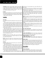
The correct procedure for checking the shaft alignment so a
boat owner can determine if service is required, is as follows:
Step 1:
Remove the bolts that secure the propeller shaft
flanges.
Step 2:
Hold the propeller shaft flange firmly against the
transmission flange.
Step 3:
Try to insert a .004" feeler gauge at the top, the
bottom and at both sides between the flanges. If
it can be easily inserted between the flanges in
any area, try inserting a larger feeler gauge until
you determine the amount of variance.
Step 4:
While holding the transmission flange, turn the
prop shaft 90 degrees and repeat step 3. A straight
shaft in proper alignment will not allow the in-
sertion of a feeler gauge larger than .004", re-
gardless of the prop shaft position.
Step 5:
If a gap larger than .004" is found and the gap
moves as the shaft flange is rotated, the flange or
the prop shaft is bent out of tolerance and must
be replaced or removed and straightened. If the
gap remains at the same position regardless of
the propeller shaft rotated position, the engine
must be realigned. At this point, a Wellcraft
dealer should be contacted.
NOTE: The boat should always be at rest in the water
when checking or aligning the propeller shaft.
MAKE SURE THE PROPELLER SHAFT FLANGE
BOLTS ARE TIGHTENED SECURELY AFTER
CHECKING THE ENGINE ALIGNMENT AND BEFORE
OPERATING THE BOAT.
NOTE: Lifting the boat with lifting straps over the prop
shafts will cause the shafts to become bent. Al-
ways position lifting straps so they are clear of
the running gear.
Propeller Shaft Coupling
004” MAX
Содержание 360 Coastal
Страница 1: ...360 Coastal Wellcraft Marine Corp 1651 Whitfield Ave Sarasota FL 34243 OWNER S MANUAL...
Страница 2: ...2 360 COASTAL THIS PAGE WAS LEFT BLANK INTENTIONALLY Print Date 8 2005...
Страница 4: ...4 360 COASTAL THIS PAGE WAS LEFT BLANK INTENTIONALLY...
Страница 16: ...16 360 COASTAL THIS PAGE WAS LEFT BLANK INTENTIONALLY...
Страница 30: ...30 360 COASTAL THIS PAGE WAS LEFT BLANK INTENTIONALLY...
Страница 36: ...36 360 COASTAL THIS PAGE WAS LEFT BLANK INTENTIONALLY...
Страница 60: ...60 360 COASTAL THIS PAGE WAS LEFT BLANK INTENTIONALLY...
Страница 64: ...64 360 COASTAL THIS PAGE WAS LEFT BLANK INTENTIONALLY...
Страница 84: ...84 360 COASTAL THIS PAGE WAS LEFT BLANK INTENTIONALLY...
Страница 102: ...102 360 COASTAL THIS PAGE WAS LEFT BLANK INTENTIONALLY...
Страница 112: ...112 360 COASTAL THIS PAGE WAS LEFT BLANK INTENTIONALLY...
Страница 124: ...124 360 COASTAL THIS PAGE WAS LEFT BLANK INTENTIONALLY...
Страница 125: ...125 360 COASTAL Appendix A SCHEMATICS 120 Volt AC Breakers...
Страница 126: ...126 360 COASTAL 12 Volt DC Breakers...
Страница 127: ...127 360 COASTAL Helm Switch Panel...
Страница 128: ...128 360 COASTAL Helm Switch Panel...
Страница 129: ...129 360 COASTAL Helm DC Breaker Panel...
Страница 130: ...130 360 COASTAL Aft Deck Panel...
Страница 140: ...140 360 COASTAL Overhead Layout...
Страница 141: ...141 360 COASTAL Side Profile...
Страница 142: ...142 360 COASTAL Trailer Support...
Страница 144: ...144 360 COASTAL MAINTENANCE LOG Hours Date Dealer Service Repairs...
Страница 145: ...145 360 COASTAL MAINTENANCE LOG Hours Date Dealer Service Repairs...
Страница 146: ...146 360 COASTAL MAINTENANCE LOG Hours Date Dealer Service Repairs...
Страница 147: ...147 360 COASTAL MAINTENANCE LOG Hours Date Dealer Service Repairs...
Страница 148: ...148 360 COASTAL MAINTENANCE LOG Hours Date Dealer Service Repairs...
Страница 150: ...150 360 COASTAL THIS PAGE WAS LEFT BLANK INTENTIONALLY...
Страница 164: ...THIS PAGE WAS LEFT BLANK INTENTIONALLY...
Страница 165: ......